
most magnetics are custom built to purpose, so unless you do one or both of the following 1) take it completely apart and do a reverse design 2) get the basic parameters AC & DC to decide if you can proceed to dynamic tests ( difficult and time consuming).What can I use them for?
it's difficult to say what you can use them for, but since they are on the small side that limits the range of possibilities.
I doubt these can be used in speaker Xovers.
unless it has a hidden gap in the core its a signal level stuff.
Thanks AJT. How do I measure inductance?
You can do it with a scope, sig gen and a capacitor and resistor.
Connect resistor in series with L and C.
Sweep the sig gen until you get min signal across the LC.
That is your resonant frequency.
L=1/( 4 (pi squared)( F squared) C)
I am always buying chokes from the bay so i find the use of an LCR meter indispensible. With such small chokes even the DCR won't give you much to go on. I have some Triad units that are slightly bigger than yours that are about 30 ohms x .3A x 1H. They are about twice as thick, though but not much bigger.
I am always buying chokes from the bay so i find the use of an LCR meter indispensible. With such small chokes even the DCR won't give you much to go on. I have some Triad units that are slightly bigger than yours that are about 30 ohms x .3A x 1H. They are about twice as thick, though but not much bigger.
FWIW, i do not buy those, i make them myself, and power traffos too for use in my amps, they are not the off the shelf items that you can find anywhere...
knowing the data let's you make a decision as to suitability of that choke to your intended use...
I tried to use a power supply 10mH inductor on the output of a class d amplifier. It very quickly got to 120 degrees c !
The core was wrong, I needed a t106-2 core for the amplifier.
I just buy in the core and the wire and wind them myself.
You live and learn.
I measure inductors with ARTA limp. It's free and only requires a simple calibration. I connect a known capasitor in series with the inductor and run impedance/electric phase measurment.The point where the electric phase change from positive to negative - or vise versa - is the resonanse frequency of the LC circuit. Write down the frequency at the exact point the electric phase crosses zero and then solve f=1/2π*sqrLC. You have to know the capasitor's value with enough accuracy. I use a 100nf - measured at 107nf actually - which is very good for measuring chokes from 20H to 1mH with ARTA limp. This way I' ve put to use many inductors that were lying around!
I tried to use a power supply 10mH inductor on the output of a class d amplifier. It very quickly got to 120 degrees c !
The core was wrong, I needed a t106-2 core for the amplifier.
I just buy in the core and the wire and wind them myself.
You live and learn.
yes, horses for courses.....
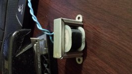
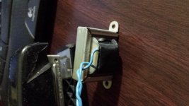
It looks similar to a tuning inductor for a vintage organ - similar size, and the winding area is not fully utilised - but it has no adjustable gap. I'm still using a large bunch of such inductors from a clapped out Wurlitzer for sneaking in some extra screen and preamp filtering under the chassis on restorations.
If your aim is for power supply filtering application then one test technique for unknown chokes that gives inductance at dc current levels is:
http://dalmura.com.au/projects/Choke measurement.pdf
If your aim is for power supply filtering application then one test technique for unknown chokes that gives inductance at dc current levels is:
http://dalmura.com.au/projects/Choke measurement.pdf
Great article!It looks similar to a tuning inductor for a vintage organ - similar size, and the winding area is not fully utilised - but it has no adjustable gap. I'm still using a large bunch of such inductors from a clapped out Wurlitzer for sneaking in some extra screen and preamp filtering under the chassis on restorations.
If your aim is for power supply filtering application then one test technique for unknown chokes that gives inductance at dc current levels is:
http://dalmura.com.au/projects/Choke measurement.pdf
A little of topic; When there is a CLCLC filter, then a "ripple trap" should apply to the first choke or to the second? Or better both?
If you had the luxury of a CLCLC filter then imho the first inductor after the rectifier may be a better position for a ripple trap - but that is an interesting query.
The 2nd harmonic level is highest on the first capacitor, and may be increased by a ripple trap, which may change the harmonic structure on that cap.
You can use PSUD2 with a stepped load to compare output voltage transient disturbance due to a dynamic load change for different values of C1,C2,C3 and L1,L2 in a C1-L1-C2-L2-C3 filter.
Layout and wiring and inductor parasitics are likely to dictate what level of output ripple/noise you end up with, or can measure.
Last edited:
Thanks for reply! I agree that the actual layout may not give the calculated results... I guess I have to test it but it's good to have in mind your suggestions. With regard to PSUD2, I do the stepped load simulation to check for overshooting. Do you think overshooting indicates 2nd order harmonics?
Transient response to a stepped load is an indication of CLCLC resonant interactions.
If you could set up a controllable load with a sinewave variation of the load (best if real, but a simulation can go a long way), and sweep through the low frequency range, then you may find 'resonant' frequencies that may be suppressed by more judicious selection of the L's and C's.
If you could set up a controllable load with a sinewave variation of the load (best if real, but a simulation can go a long way), and sweep through the low frequency range, then you may find 'resonant' frequencies that may be suppressed by more judicious selection of the L's and C's.
- Status
- This old topic is closed. If you want to reopen this topic, contact a moderator using the "Report Post" button.
- Home
- Design & Build
- Parts
- I assume this is a choke.