And what issues are there with the grounding shown in the photos I have posted?
The Yellow/green wire is not securely attached to the chassis. On most China-sourced low-cost amplifier is missing althogheter, so yours is a better outcome but still a electrical code violation. The grounding screw should not be used for other purposes (on your amp, is a part of the plug receptacle); the wire should be attached to a electrical terminal (not directly soldered); the screw should have a mechanical retainer to avoid accidental unscrew. The resistence from the plug to the chassis should be less than 0.1 ohms.
the resistance in this case should not be an issue unless the solder is so bad.Without a micro-ohm meter it not possible to measure this low value.
Definitely connection should be direct on to the chassis with a lug and double nuts on a separate stud as pcan mentioned above. If not drill a hole and fix a screw with double nuts and washer to hold the lug.
Definitely connection should be direct on to the chassis with a lug and double nuts on a separate stud as pcan mentioned above. If not drill a hole and fix a screw with double nuts and washer to hold the lug.
Thanks all
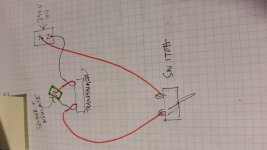
Ive attched a sketch to make sure I understand the wiring. I dont think I have a second lug on the switch but I will connect the neutral to it in the same way if i do
Ill buy a lug and drill a new hole at the back of the chassis to connect the grounding wire
ps Will the primary wires have an enamel(?) coating that needs to be sanded / filed off before soldering?
Attachments
Last edited:
Most likely, all those cheap Chinese El-Core transformers are all using solid core enamel/varnish coated winding wiring. Sand/scrap it down to the bare metal base, twist the pair together and heatshrink it.
I would sort out that IEC ground as well as others have suggested, get a crimp on the end and bolted through the chassis properly.
I would sort out that IEC ground as well as others have suggested, get a crimp on the end and bolted through the chassis properly.
As DefQon said above enamelled wire is used for the winding. Enamel is required to insulate between each turn. All motors, transformers use enamelled wires. Only when you go up the voltages (the pole mounted transformers or the substations supply you power) that insulation becomes complicated.
What you see as red and black are PVC insulated copper wires (tinned or bare copper). These are soldered to the winding inside and enamelled wires are not be visible to you. You may need to scrape to remove any oxide from the PVC leads before soldering. As these wires are already soldered ( 2 to the blue wires to the switch and 2 to the socket) even scrapping may not be required.
Some manufacturers bring out the enamelled wires and solder them to terminals fixed on the plastic bobbin on which they wind the wires. Some leave them out without terminals or extended insulated copper wires. Only in this case you need to clean them to shiny copper before soldering.
Hope this helps.
Last edited:
This is how a safety ground connection should be.
An externally hosted image should be here but it was not working when we last tested it.
- Status
- This old topic is closed. If you want to reopen this topic, contact a moderator using the "Report Post" button.
- Home
- Design & Build
- Parts
- ID help - is this is a 110v or 220v transformer