")
The 3rd Harmonic performed 30dB worse
Hello All,
I did a little digging and found that Audio Precision uses, Tripp Lite USB 2.0 Hi-Speed A/B, USB cables for their test equipment.
I repeated the QA401 analyzer tests of silver plated wire vs a mil-spec resistor. This time I used the Tripp Lite USB 2.0 Hi-Speed A/B USB cable.
The silver plated copper wire 3rd Harmonic performed 30dB worse than the Dale Vishay resistor. This could account for reported harsh sounding silver plated performance.
This needs additional tests and reports.
DT
Attachments
Too much feast.
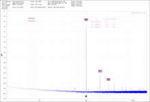
Reconnected everything to the old school AP2522 on my bench and got the same results. There is about a 30dB increase in 3rh harmonic distortion compared to a similar value Vishay Dale mil-spec metal film resistor.
A little repeat; the snarl of silver plated 22AWG wire that I am testing is 100 plus feet long and measures 8 ohms resistance. The ball of wire is placed in a steel hinged cover junction box to isolate noise.
See the attached pdf.
DT
Attachments
A wire 100+ feet long will have some inductance and capacitance. Who knows the steel box may also have an effect. Steel box AKA isolation enclosure, chassis. We all put our project in enclosures. This particular box is a Hoffman NEMA Type 1 enclosure.
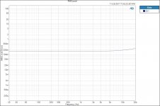
I ran RMS Level Sweeps with the silver plated wire both inside and outside the enclosure. The plots were identical, no difference. See the inside the box plot below.
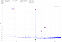
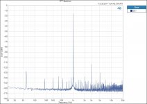
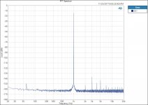
I ran FFT’s with the silver plated wire both inside and outside the enclosure. The plot outside the box has considerable interference. The plot inside the box has the same harmonics minus most of the interference. See the plots below.
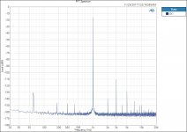
For comparison I ran a FFT on a mil-spec resistor with a resistance similar to the silver plated wire. See the plot below.
There is something going on with that length of silver plated wire.
DT
I ran RMS Level Sweeps with the silver plated wire both inside and outside the enclosure. The plots were identical, no difference. See the inside the box plot below.
I ran FFT’s with the silver plated wire both inside and outside the enclosure. The plot outside the box has considerable interference. The plot inside the box has the same harmonics minus most of the interference. See the plots below.
For comparison I ran a FFT on a mil-spec resistor with a resistance similar to the silver plated wire. See the plot below.
There is something going on with that length of silver plated wire.
DT
Attachments
You need to go hunting for reasons why you get such a strange result. If silver plated copper gave this level of distortion for RF then this ought to be noticeable in communications systems. Try different frequencies. It is just possible that you are seeing a thermal effect.
In any case, the result tells us nothing about audio interconnects - which are a trivial potential divider. Wire would have to be much worse in your test to affect audio.
In any case, the result tells us nothing about audio interconnects - which are a trivial potential divider. Wire would have to be much worse in your test to affect audio.
If you want a single number to represent the Teflon insulated silver plated wire test results, here it is.
0.0019% THD+N. (over 100+ feet of wire)
That is a tiny number and a very long piece of hook up wire. We will let others argue if that is audible or not.
I do not believe that I need to go hunting for reasons. Earlier in this thread I speculated about the reasons. The speculations centered around dissimilar metals and thermal effects.
DF96 you are exactly correct about the effect being trivial for audio frequencies over short lengths of wire.
The short version according to DT is; do not pay extra for Teflon insulated silver plated wire.
DT
I would add a few extra zeros, comparing the inductance of a less than 2 feet straight piece of wire which is what a connecting wire inside an amplifier is, and a huge inductor made out of hundred(s) turns of wire, 100 feet long if unrolled.
Usually I can´t follow a ruler straight line inside an amp if going from point A to point B, some zigzagging can be required (which tends to be self cancelling anyway) , but I definitely won´t look for trouble by winding a dozen or 100 turns of it to make a coil.
Usually I can´t follow a ruler straight line inside an amp if going from point A to point B, some zigzagging can be required (which tends to be self cancelling anyway) , but I definitely won´t look for trouble by winding a dozen or 100 turns of it to make a coil.
Wide peak in the THD+N plot
DF96,
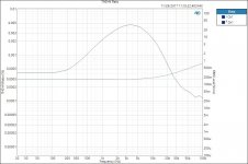
You ask about distortion at other frequencies. I ran a 20 Hz to 100 KHz THD+N % sweep. I was surprised with the result.
Centered at about 3.5 KHz there is a wide peak in the THD+N plot. This level of distortion is similar to the distortion attributed to polyester film capacitors.
See the attached Teflon insulated silver plated wire THD+N % plot
DT
DF96,
You ask about distortion at other frequencies. I ran a 20 Hz to 100 KHz THD+N % sweep. I was surprised with the result.
Centered at about 3.5 KHz there is a wide peak in the THD+N plot. This level of distortion is similar to the distortion attributed to polyester film capacitors.
See the attached Teflon insulated silver plated wire THD+N % plot
DT
Attachments
If you want a single number to represent the Teflon insulated silver plated wire test results,
here it is. 0.0019% THD+N. (over 100+ feet of wire)
Did you test a shorter piece of wire to see if the distortion scales with length?
Did you test a shorter piece of wire to see if the distortion scales with length?
I suspect that it will scale with length.
I will give it a try.
DT
Hello,
I shortened the wire.
I am thinking that Teflon insulated silver plated wire does not make a very good resistor.
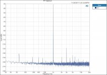
The silver plated wire appears to generate 3rd harmonics and to a lesser extent 2nd Harmonics. As the wire gets longer inductance and possibly capacitance begin to have an effect as well. As I reduced the length of the silver plated wire the peak in the distortion shifted to frequencies above 20 kHz and reduced in magnitude.
As the wire got shorter the voltage drop over the length of wire reduced proportionally. The FFT profile reduced in magnitude. The relative heights of the harmonics reduced proportionally with the reduction in voltage drop over the shortened length. As the overall resistance of the silver plated is reduced the FFT signature remains the same with a much reduced magnitude.
Short condensed version. If you use long, small diameter, speaker wires you may begin to hear the silver plated distortion signature. If you use short lengths of hookup wire inside your amplifier you will not begin to hear it.
See the attached plot. The silver plated wire is reduced to about 20ft.
DT
I shortened the wire.
I am thinking that Teflon insulated silver plated wire does not make a very good resistor.
The silver plated wire appears to generate 3rd harmonics and to a lesser extent 2nd Harmonics. As the wire gets longer inductance and possibly capacitance begin to have an effect as well. As I reduced the length of the silver plated wire the peak in the distortion shifted to frequencies above 20 kHz and reduced in magnitude.
As the wire got shorter the voltage drop over the length of wire reduced proportionally. The FFT profile reduced in magnitude. The relative heights of the harmonics reduced proportionally with the reduction in voltage drop over the shortened length. As the overall resistance of the silver plated is reduced the FFT signature remains the same with a much reduced magnitude.
Short condensed version. If you use long, small diameter, speaker wires you may begin to hear the silver plated distortion signature. If you use short lengths of hookup wire inside your amplifier you will not begin to hear it.
See the attached plot. The silver plated wire is reduced to about 20ft.
DT
Attachments
The silver plated wire is reduced to about 20ft.
Also, what kind of terminations did you use?
Also, what kind of terminations did you use?
The DUT was an 825R resistor soldered is series with ~20 feet of 24AWG Teflon insulated silver plated wire. The resistance of the wire is about 2ohms.
The test leads are BNC on one end an red &black mini-grabbers on the other end. The 2 black grabbers clip free end of the wire. The red grabber from the APx output clips to the free end of the resistor. The other red clip clips at the junction of the resistor and wire.
The entire mess is placed in a grounded isolated box. And press the start button.
DT
The DUT was an 825R resistor soldered is series with ~20 feet of 24AWG Teflon
insulated silver plated wire. The resistance of the wire is about 2ohms.
Have you tested any standard tin plated copper wire (or enameled magnet wire)
of a similar size for comparison, using the same setup?
Last edited:
- Status
- This old topic is closed. If you want to reopen this topic, contact a moderator using the "Report Post" button.
- Home
- Design & Build
- Parts
- Chassis wire