As an owner of a Marantz PM80SE, it has given me the usual grief of a failing STK3102, twice.
Thanks to this forum, I quickly found it to be the culprit when it first statrted acting up in 2004. And then it started all over again in 2011.
Not wanting to replace the module I again, I thought about making a discrete replacement based on the VAS of PM8000, which looked like it should work without too much headaches. But I stashed the amp in the attick instead and never made an attempt.
After some work on my brothers PM7200KI, I thought to have another go again.
Powered it up and sure enough, the output relays refused to engage.
A quick measurement on the headphone voltage divider near the red reed relay at the back of the power amp board confirmed the left output going close to a voltage rail.
Took out the STK3102 (or so I thought) and powered it up again, no more DC.
Since the replacement STK-module that I bought in 2004 was no longer functioning properly, I popped the plastic cover and found that it was a fake. Finding only SOT23 transistors and some 0805 resistors, I was a bit surprised. Okay, in a VAS it worked for about 6 years, but aren't these things supposed to be able to drive 8 Ohm loads?
This is apparently the inside of an oriniginal:
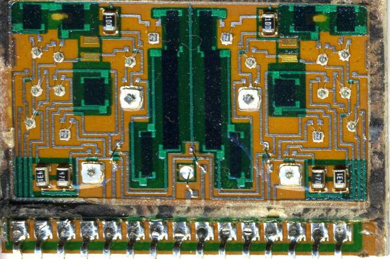
Whereas in my (supposedly) STK3152 replacement it looked like this:
Front of the fake:
Rear of the fake:
No doubt many of you know about these replacements being fake, but I thought I'd share it anyway.
I do wonder, though, if I can repair this thing and stick it back in...
Hopefully these transistors aren't some Chinese knock-offs but generic transistors that I can find in a smd-codebook..
Thanks to this forum, I quickly found it to be the culprit when it first statrted acting up in 2004. And then it started all over again in 2011.
Not wanting to replace the module I again, I thought about making a discrete replacement based on the VAS of PM8000, which looked like it should work without too much headaches. But I stashed the amp in the attick instead and never made an attempt.
After some work on my brothers PM7200KI, I thought to have another go again.
Powered it up and sure enough, the output relays refused to engage.
A quick measurement on the headphone voltage divider near the red reed relay at the back of the power amp board confirmed the left output going close to a voltage rail.
Took out the STK3102 (or so I thought) and powered it up again, no more DC.
Since the replacement STK-module that I bought in 2004 was no longer functioning properly, I popped the plastic cover and found that it was a fake. Finding only SOT23 transistors and some 0805 resistors, I was a bit surprised. Okay, in a VAS it worked for about 6 years, but aren't these things supposed to be able to drive 8 Ohm loads?
This is apparently the inside of an oriniginal:
Whereas in my (supposedly) STK3152 replacement it looked like this:
An externally hosted image should be here but it was not working when we last tested it.
Front of the fake:
An externally hosted image should be here but it was not working when we last tested it.
Rear of the fake:
An externally hosted image should be here but it was not working when we last tested it.
No doubt many of you know about these replacements being fake, but I thought I'd share it anyway.
I do wonder, though, if I can repair this thing and stick it back in...
Hopefully these transistors aren't some Chinese knock-offs but generic transistors that I can find in a smd-codebook..
That's just the point, it DID work as a front end stage in the PM80SE for about six years, so you can imagine my surprise finding the SO23s. This amp drives the speakers through discrete BJTs which are in turn driven by the STK-module.
I agree that when this replacement would have been used as a power amp that it would probably have failed immediately.
I agree that when this replacement would have been used as a power amp that it would probably have failed immediately.
Here is something interesting :
We all expect one to replace the 3102 , check soldering , check the known relays issue ,replace a few capacitors , set the bias and done...
I also expect "techs " that simply replace the 3102 and give away .
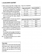
Point is that in the first case and when one wants to set the bias will look at the service manual and bias the amplifier accordingly .The problem is that the service manual is written WRONG !!
It states that at bias points bias should be 18mv over a resistor 0.18R and that equals to 50ma ......Obviously this wrong since this equals to 100ma
farther more in the high bias condition 198mv over a resistor of 0.18 that equals to 500 ma Obviously this is also wrong and equals to 1A
Pm 80 features both neg and pos test points and what the missed to print is that the sum of the two redings ( pos +neg ) should be 18mv and 198 mv respectively .
Cannot tell if more than double the bias will stress the IC but obviously in total the heat will stress the amp and produce fatigue of parts and soldering .
Now days fake IC exist from PMC /SAN which the quality i am not aware off so i replaced one , added a far better heat sink and bias the amplifier properly to see how far i will go ....
Enjoy a print of the schematic
Kindest regards
Sakis
We all expect one to replace the 3102 , check soldering , check the known relays issue ,replace a few capacitors , set the bias and done...
I also expect "techs " that simply replace the 3102 and give away .
Point is that in the first case and when one wants to set the bias will look at the service manual and bias the amplifier accordingly .The problem is that the service manual is written WRONG !!
It states that at bias points bias should be 18mv over a resistor 0.18R and that equals to 50ma ......Obviously this wrong since this equals to 100ma
farther more in the high bias condition 198mv over a resistor of 0.18 that equals to 500 ma Obviously this is also wrong and equals to 1A
Pm 80 features both neg and pos test points and what the missed to print is that the sum of the two redings ( pos +neg ) should be 18mv and 198 mv respectively .
Cannot tell if more than double the bias will stress the IC but obviously in total the heat will stress the amp and produce fatigue of parts and soldering .
Now days fake IC exist from PMC /SAN which the quality i am not aware off so i replaced one , added a far better heat sink and bias the amplifier properly to see how far i will go ....
Enjoy a print of the schematic
Kindest regards
Sakis
Attachments
a point of verification
I just completed a very similar experience replacing (for the second time) the STK3122-3 in my Marantz TA170AV. Like the OP, I was surprised to find that my replacement had been a counterfeit and that it had actually endured a nonzero lifespan.
I dissected both parts, took some pictures, and did a casual writeup of my findings and conjectures on my disused blog before finding (and referring to) this thread.
I figured I'd share what I found because I feel it reveals a fairly reliable method to identify the counterfeit parts. Often a good set of photos is sufficient, and this makes online shopping marginally less uncomfortable. To quote myself:
While dissecting the fake doesn't help us better understand the original Sanyo part's internals, it does offer some information that will help make counterfeits identifiable. There may be more than one breed of counterfeit out there, but I have been able to identify current Ebay listings which match this particular type.
- The counterfeit appears to have a facility to allow pin 8 to be bonded to the aluminum substrate, although in the example I have, there is no substrate connection at all. Counterfeit parts may lack continuity between pin 8 and the aluminum substrate.
- The leads of the original Sanyo part are an iron alloy (magnetic), whereas the counterfeit leads are nonmagnetic.
- The original leads also have a sheared shoulder near the package connection. In the photos, it's easy to see that the leads are slightly wider near the bend. The leads on the counterfeit are formed differently and have a uniform width.
- It's also worth noting that any legitimately NOS parts will likely have heavily tarnished lead plating. It's not a sure thing, but shiny beautiful leads are an indicator. If you're buying a pulled part, who knows what kind of shape the leads will be in.
- The orange substrate insulation of the genuine part is visible through the lead apertures in the molded plastic shell. This is particularly easy to see in the empty opening for pin 16. The counterfeit part is just a MCPCB and simply shows bright green solder mask everywhere.
- Finally, the easy way to spot some fakes is as simple as looking at the date/lot code on the front of the part. The counterfeit part I disassembled has a code 5302. Checking Ebay, I can find at least two "Genuine Vintage NOS" parts which have green solder mask, shiny leads, and a 5302 date code.
Last edited:
I just took a closer look at your photos. It's difficult, but the package marking codes are visible. Although your part was sold as a STK3102, it is identical to the one I had marked STK3122.
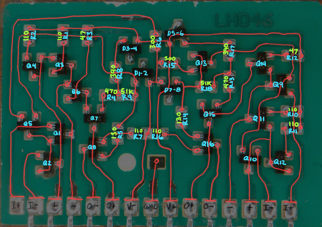
The transistors are rated for 160v. The NPN transistors marked with G1 are MMBT5551, and the PNP transistors marked with 2L are MMBT5401. The diode pairs are marked A7, and are BAV99. These are all super-common general purpose parts.
Concerning power dissipation of the small parts, I added a bit of analysis to my previous blog post on the matter. Since the circuit values are known, I simply ran a simulation on a single channel. At the bias point in my application, the dissipation on R9/R18 is around 300mW. The dissipation on the output transistors is about 380-400mW each. Considering the MCPCB substrate, this is probably within allowable limits, though I'm still inclined to use a heat sink for good measure.
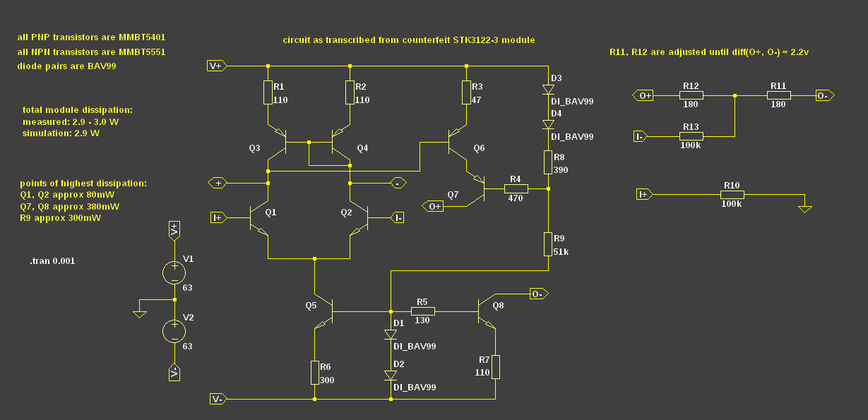
Of course, none of this says anything about whether the module can meet noise or distortion specs. If a person weren't terribly picky about signal integrity, it's interesting to know that these counterfeit modules are entirely repairable. I'm assuming mine failed due to lead plating failure, but it would be nice to know if there were other known modes of failure among these parts.
The transistors are rated for 160v. The NPN transistors marked with G1 are MMBT5551, and the PNP transistors marked with 2L are MMBT5401. The diode pairs are marked A7, and are BAV99. These are all super-common general purpose parts.
Concerning power dissipation of the small parts, I added a bit of analysis to my previous blog post on the matter. Since the circuit values are known, I simply ran a simulation on a single channel. At the bias point in my application, the dissipation on R9/R18 is around 300mW. The dissipation on the output transistors is about 380-400mW each. Considering the MCPCB substrate, this is probably within allowable limits, though I'm still inclined to use a heat sink for good measure.
Of course, none of this says anything about whether the module can meet noise or distortion specs. If a person weren't terribly picky about signal integrity, it's interesting to know that these counterfeit modules are entirely repairable. I'm assuming mine failed due to lead plating failure, but it would be nice to know if there were other known modes of failure among these parts.
Hi guys,
I found this topic because I have been restoring two pieces of Philips FA960 amplifiers, which are close brothers from the Marantz PM80. These also feature the STK3102 (STK3152) as a driver. One of the amplifiers had a defective driver STK so I needed a replacement. Along comes the question: where to buy genuine high quality STK modules in the 21st century?
Being a repairsman and having access to all business wholesale suppliers I soon found out that this is not an easy task. Only one of my suppliers carries the STK modules on stock and yes these are the SAN/PMC ones. This is as far as I know the only way to obtain new STK replacement drivers.
Pulled pieces are available on ebay as well as new-old-stock. But as mentioned before, the quality of these parts may be highly disputable. So, this actually does not leave us much choice, does it?
That being said, I am arguing that the parts mentioned before as being "counterfeit" are in fact the only alternative we have these days. Only if for example Toshiba or any other big supplier would be able to produce "real genuine" STK modules, one could say that the others are counterfeit. But if the original is no longer available, doesn't that make the only alternative a closest match?
Something to think about while my FA960 is playing and waiting for me to adjust the quiescent current...")
I found this topic because I have been restoring two pieces of Philips FA960 amplifiers, which are close brothers from the Marantz PM80. These also feature the STK3102 (STK3152) as a driver. One of the amplifiers had a defective driver STK so I needed a replacement. Along comes the question: where to buy genuine high quality STK modules in the 21st century?
Being a repairsman and having access to all business wholesale suppliers I soon found out that this is not an easy task. Only one of my suppliers carries the STK modules on stock and yes these are the SAN/PMC ones. This is as far as I know the only way to obtain new STK replacement drivers.
Pulled pieces are available on ebay as well as new-old-stock. But as mentioned before, the quality of these parts may be highly disputable. So, this actually does not leave us much choice, does it?
That being said, I am arguing that the parts mentioned before as being "counterfeit" are in fact the only alternative we have these days. Only if for example Toshiba or any other big supplier would be able to produce "real genuine" STK modules, one could say that the others are counterfeit. But if the original is no longer available, doesn't that make the only alternative a closest match?
Something to think about while my FA960 is playing and waiting for me to adjust the quiescent current...
As I'm clearing some of my old equipment that's just been gathering dus, it was time to revisit this thread and see about reviving my Marantz PM80SE.
Dead, it won't be of much value to anyone (not even to repairmen, I have already seen one of them deeming a (Mk I) PM80 or PM80SE unrepairable if the STK-module had failed.
I'm stuck with this fake module. But even though it's fake, it does the job.
Thanks to alumasqrl's reverse engineering (thanks for that!), I decided to check the components on the little board, and they all checked out. Under the microscope, some of the solder joints looked like they could have been done better. Not sure if there were any cracks, though, but I resoldered them anyway and put the module back in the amp.
After power on, the speaker relays clicked. I'm going to do a little endurance test, to see if it fails again, or if the resoldering did the job.
If it passes, I will still have to buy a new speaker relay, the one in Channel 1 doesn't work on the right channel. I flipped out the top part of the relay to find one of the contacts blown to pieces. So no sanding the contacts and putting it back in this time.
Kenwood uses the STK module also
I have two kenwood KAC-901 amplifiers. I really like the amp, but like you have had to replace the STK module a couple times. As I recall the module use to cost 20.00 or so, and now they have cost me 4.00 I bought two parts off of fleabay.
When I was running the amps What I found was an over heating problem with the module. I am assuming they are the same type amplifier design, funny how all the designers use almost the same design all the other designers use for that period.
Anyway, the module I have is a 90watt per channel unit. The module drives the final output transistors that provide the POWER for the speakers. I don't believe this model of the STK module was ever designed to power the speakers, but to only power the final output transistors, regardless, this module would NEVER drive a speaker. So look at your schematics, and I believe you will see that the module drives the output transistors.
The module ALWAYS got to hot and went bad after driving the amp into saturation, or wide open for extended periods.
What I ended up doing was to do as one person said, and provided a heat sink for the part. It was a simple fix at the time with a radio shack TO247 heat sink black anodized with fins on each side. I used heat sink compound, and a tie wrap to hole the heat sink to the part, that was my initial test of the part, and it worked, so I never did anything more to the amp. I had all these plans about how I could use an aluminum bar across the amp housing and secure the part with a machines strap, but that was not needed. So you may want to give that a try, and maybe they are "counterfit" parts, but they are essentially the same part, and both parts, "counterfit" and original parts sucked LOL.
anyway just my O2 here.
Take a look at the PM-80 schematic here
http://www.pascalchour.fr/ressources/marantz/pm80-schema1.jpg
Apart from the error in the optocoupler LED polarity in the output bias, you can see that the driver module sees 100R in series with the output bases. When in clipping, the driver "54V" can easily be above the outputs "56V", due to the RC filters and high currents will then flow.
..same troubles with a SONY TA-F550ES..
For those, who are interestet in..may the force* be with you..
Hi fmmech24,
the STK3102/III is also used in the SonyTA-F530ES, which i have on my repair bench. Regarding your schematics, which diodes you use for the one named 'double' and what does the asteric on several resistors mean. Any pictures of a built module available, that i can see the cooling mechanic. Ordered already a few pcbs at JLBCB.
Best regards
Günni
Does anybody know about R10/11/12&13 in post #6? These are possibly visible in the first post photo, I can see a trimmed resistor at the top, but not present in the clones in #6 or #11
There is also no trace of them in the original Sanyo data sheets.
Looking at the TA-530 service manual, these components would mess up the operation, especially the 100k R13 and might prevent amplifiers with output triples from being biased on.
There is also no trace of them in the original Sanyo data sheets.
Looking at the TA-530 service manual, these components would mess up the operation, especially the 100k R13 and might prevent amplifiers with output triples from being biased on.
Answered myself, they are dummy parts for LTSpice.
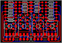
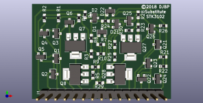
This is an uprated substitute using SOT-223 output devices and splitting the high dissipation "51k"
Anybody who wants to use this, make a donation to a charity of your choice
This is an uprated substitute using SOT-223 output devices and splitting the high dissipation "51k"
Anybody who wants to use this, make a donation to a charity of your choice
Attachments
Last edited:
DZT5551 for the npn
PBHV9115Z for pnp
The original "clone" board is a very good design, I found it hard to change anything without requiring jumpers or vias, but I wanted to keep the B side substrate only. The clone was flawed using SOT-23 as the npns are slightly over run and the pnps can be really pushed by the external driver load. Squeezing in SOT-223s was tricky.
I can improve this board further by adding copper to the outputs collectors
Attachments
Last edited:
- Home
- Design & Build
- Parts
- Fake STK3152/STK3102