I get irritated when I break a carbide bit, (went so far as to buy a new drive for my Grizzly mill, abandonding the Dremel.) SMD makes it so much quicker -- but you do have to take the time to lay out and make a PCB. I use Kester solder paste and a Black and Decker toaster oven.
I avoid using SMD electrolytics, had problems with many of them. I tried using SMD potentiometers for trimmers, and now stick with Bourns 3296W. I have a Jameco SMT resistor kit which is really handy, but would suggest purchasing caps new from the usual suspects.
My first SMD project was the phase detector/meter from Intersil which used one of their SMD transistor matrices and CFB amps. While I had some through-hole CFB opamps I decided to go smd for as much as the project as possible -- works beautifully and a really small footprint.
When it comes to some of the really small devices -- like Linear's true RMS detectors, I cheat and buy a development board. I have one fitting into an HP403dB meter and it's accurate to 1MHz.
Good capacitors in SMD are NP0 (for ultra-low loss, great stability) and X5R (for very high density of capacitance per unit volume, exceeding many electrolytics at lower voltages). Bad SMD caps in my experience are the electrolytics - I've found through-hole to be superior in ESR terms for same can size.
SMD resistors are something of a mixed bag - thick film are OK in lowish values when physically small, but excess noise quickly climbs at higher resistances. I tend to only use 1206 above around 10k or so. Thin film are pretty good but can easily be put out of tolerance with excess heating from soldering.
Inductors are the most difficult components to shrink of all. I've found it practically impossible to find very high Q (say above 40) in SMT and values into double digit mH are equally problematic.
I think you have mixed up your info: AFAIK thin film aka. metal film are more stable compared to to thick fill - ?
\\\Jens
I have been hand-soldering small 44-pin-quad flat-packs (CS3318) several times. I just brutally solder everything without care for shorts, then go around with the solder wick. Sounds maybe counter-intuitive but my results have been 100% perfect physically and electrically every time.
Jan
Jan
How do you stop these tiny fleas from sticking to the iron?
I use an SMT tweezer: Googles billedresultat for http://www.hin.dk/images/Products/BAHCO/5549-t.jpg
This enables you to rest your hand on the table while soldering - you can get good results this way
")
\\\Jens
The chip inside the case is always going to be small, the SMD package just makes the chip more accessible. High power components will always be big but the smaller SMD devices are so much easier to use. I use a crocodile clip with flattened cocktail sticks to hold the flea in place during soldering.
I think you have mixed up your info: AFAIK thin film aka. metal film are more stable compared to to thick fill - ?
Just reporting my experience - I haven't had thick film go out of tolerance when soldering at too high a temp (forgot to reset my iron's temp back to normal after doing some major desoldering). At normal temps, yes metal film is more stable, better tolerance.
I use Kester solder paste and a Black and Decker toaster oven.
Genius!
I have done a lot of work with SMD parts over the years. All of the boards my company produces are SMD, and when I do new designs I make the first few prototypes by hand. The finest pitch parts I have worked with are 025 pitch.
The trick is to use a cheap toaster oven. Don't use the good ones, they heat up too quickly. And, don't use your wife's toaster oven. Find a cheap one at a garage sale or thrift store.
Apply solder paste to the SMD pads using a toothpick or small wire. It takes very little paste to make a good connection. If you apply too much, the solder will just ball up and with fine pitch parts, it will bridge to the adjacent pad.
Place the parts on the board using tweezers doing your best to line things up straight. It is not that critical for most parts, but more so for the fine pitch ones. When the board is heated, the surface tension of the wet solder will help to self-align the parts on the pads. If the fine pitch parts are not aligned well to start, they may self-align one pad off.
Place the board in the center of the oven and turn it on to "Bake" at 200 deg F for 4 minutes. This will bring all the parts up to a low working temperature. If you err on the time, err on a longer soak time at 200 deg.
Raise the temperature setting to 325 deg F for 2 minutes. This will allow the internal temperature to begin to rise without becoming too hot.
Finally raise the temperature setting to 450 deg F. Watch the board carefully. In my oven the solder will start to melt after 45 sec to 1 minute depending on the lead size of the part. Heavy parts with large leads will take longer as their thermal mass in higher. Watch the time closely. From the time the solder melts, leave the oven at 450 for only 30 seconds, then turn off the oven and open the door. This will allow sufficient time for the solder to wet the joint without overheating the part's die.
The boards will be hot, and the solder joints will need time to cool. Let the board sit for 5 to 10 minutes until it is cool enough to handle.
Inspect the board closely using a lighted magnifier if you have one. If there are solder bolls, just pick them off using tweezers or small-nose pliers. They should pop right off. Sometimes an SMD part like a small resistor may ride up on top of the solder, never making a joint. Touch this up with a fine tipped solder iron. On fine pitch parts if there was too much paste, you may find a solder bridge across tow leads. Use some fine solder wick and a fine-tip iron and the bridge should come off easily.
Good luck!
How do you stop these tiny fleas from sticking to the iron?
First tin one pad, the side that is easiest to get to with the iron. Use a small flat head (anodized so solder is not as likely to bond to the tip) screw driver ~2mm. Dab the tip is solder flux and stick the tiny 0402 part to it. This allows you to hold it in place to solder the one side. Then simply solder the other. I use the same method with other tiny SMDs like SOT-563 or SOT-923 (0.8mmX0.6mm)
 .
.Many of us who have actually made the effort to learn can manually solder SMD parts down to 0805 and SOP package styles without too much difficulty. It DOES take patience, time to learn, and a modest investment in new tools.
Dale
I have soldered 0201 and 0402 array resistors using the method above.....and some magnifying headgear.
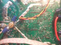
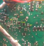
In my EC mosfet stereo amp there are a variety of smaller SMDs used. Some of them I labeled so you can see relative size.
Attachments
Last edited:
I'm reviving this thread, don't know if you guys after 10 years are still here, but wanted to know if your opinions on SMT vs TH are still the same.
My only concerns about SMT components is about how they are (or not) designed to work for Audio Power Amps. In 10 years a lot has probably changed, and I suppose manufacturers have decided to make their components suitable as well for this applications.
I'm not worried about how small they are, I have the proper tools for them.
My only question is, for a full discrete audio amplifier, go full TH or full SMT? Are nowadays transistors as good as the good old 2240s? Or for a full discrete amplifier, the difference on "sonic" some audiophiles tend to say about transistors have, would make such a difference using SMT?
Actually that was 3 questions
Thanks
My day job involves designing and building power amplifiers in the 1kW class using SMT components where possible. The notable exceptions would be connectors, high value/voltage electrolytic capacitors, CM chokes and transformers.
So the answer is: use the most appropriate technology for your design and manufacturing capability.
There are SMT equivalents of most PTH parts. In terms of transistors, the same die is used, it is just the package that changes.
Performance can be significantly superior due to reduced parasitic associated with the leaded packaging or worse due to reduced power handling.
It is really your choice. You can choose rubbish parts in either TH or SMD. It isn't difficult to find quality in either format. Naturally there is a cost premium in some (but not all cases)So apart from some capacitors, SMD components don't make much of a difference when compared to TH components in terms of sound quality these days...
Apart from electrolytic capacitor and class A/AB driver/output device, I prefer SMD part. They are space-efficient both in storage and especially PCB. Soldering and Desoldering SMD part is much more faster and convenient than THT part, and desoldering SMD part is far less likely to damage the PCB too.
- Home
- Design & Build
- Parts
- SMD vs through hole