Yep, I just run the output wire out of the chassis and then connect to the speaker wire right there.
And yes, could be used internally too. They're ul certified and can take over 300v of continuous electricity... and a 1kA pulse.
Interesting, thanks.
Zu says there is copper content in the brass for better conductivity....
You’re thinking of Bronze. Brass is an alloy of copper and zinc and it’s not a good conductor.
So Zu's claim is technically correct. (Except: better than what? Iron? Silicon steel?)
Bronze is not the best but FAR from the worst conductor.
Electrical Conductivity of Materials - Blue Sea Systems
Say 28% of Copper. You can make the conductor twice the diameter, or a quarter the length, and be the same Ohms as copper. For wire, not economic. But in *connectors* the diameter is often set by mechanical strength or user finger-fatness. I've put a lot of 1/16" wire through 3/8" lugs. And wires dozens of feet long opposed to less than an inch of alloy.
The composition of binding posts really is an audiophile’s journey in nit picking. I’m sure I’ll be happy with the Zu Audio posts. Appreciate your input.
Bit of info that may be useful to future visitors here:
The sheet screw holes to affix the top and bottom panels are threaded to M3 specs. To affix the standard plastic feet using the same holes as for the bottom panel, substitute M3-16 machine screws for the black sheet metal screws provided.
The sheet screw holes to affix the top and bottom panels are threaded to M3 specs. To affix the standard plastic feet using the same holes as for the bottom panel, substitute M3-16 machine screws for the black sheet metal screws provided.
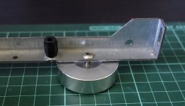
As suggested by Zen Mod (tray spacers), and the queries on feet mounting, the attached photo provides an idea of what I have done
1) A 12mm spacer has been added (a 'dummy' at this stage - it's plastic) as an internal tray spacer.
2) The front and rear pre drilled screw holes (that hold the upper and lower bases in position) of the base have been tapped to M4 and M4 bolts screwed in from above. This allows one to screw on the feet, after having placed the base plate in position. The middle plate screw is still used as per design whilst the feet clamp the 4 corners of the base in place. Obviously the 4mm screw size must be chosen such that it is not too long to prevent the feet 'clamping' the base plate in position. The M4 bolt length will probably vary by which feet are used (I purchased mine from Ebay).
Anyway, I thought this idea might be helpful to others.
Attachments
So, my top, bottom, and back are NOT flat. All three have "sides." Roughly 1/2" edges bent 90 degrees to the panel. Top and bottom are not symmetric. The "sides" are notched on one edge. I can provide pictures, but I hope that I'm not the first with this setup.
I'm currently concerned with the back panel. Should the edges stick out or stick in? The diagram from the manufacturer appears to show a flat panel, so it isn't much help.
Cheers.
I'm currently concerned with the back panel. Should the edges stick out or stick in? The diagram from the manufacturer appears to show a flat panel, so it isn't much help.
Cheers.
Yes, that's how they should be.
The 'overlaps' (90° 'edges') are mounted at the front and back of the case.
Note that the bottom/top panels are identical but fit one way only - you can't rotate 180° (otherwise the predrilled holes won't align).
At the rear the overlap is outside the chassis, holding the rear panel in place.
At the front the overlap is inside the chassis and forms part of the 'base' to which to attach the front panel.
If you just align the holes of the top and bottom panels with the chassis it is quite easy to see how they fit in place.
HTH
Most of the pics don't work on the first post anymore. Anyone have an updated assembly guide?
Got my chassis today. It came with a small black and white schematic print out. Not helpful for putting together this very expensive chassis, not super thrilled.
EDIT: found original pics/build guide using waybacktimemachine
Got my chassis today. It came with a small black and white schematic print out. Not helpful for putting together this very expensive chassis, not super thrilled.
EDIT: found original pics/build guide using waybacktimemachine
Last edited:
Most of the pics don't work on the first post anymore. Anyone have an updated assembly guide?
Got my chassis today. It came with a small black and white schematic print out. Not helpful for putting together this very expensive chassis, not super thrilled.
EDIT: found original pics/build guide using waybacktimemachine
Here's the link for anybody else looking for all the pictures in 2021 and beyond.
Actually, I found putting this together is pretty straight forward.
Important is to not tighten the covers before the chassis is „complete“, and especially not to tighten the eventually present inner baseplate—its construction is so that the heatsinks are bent outwards, and after the cover is placed, the baseplate is bent downwards...
Furthermore, I recommend a test-build and evaluation of the build-order and screw-placement/-type. Not every screw will be accessible when everything is in place.
How did you attach the chassis feet? As far as I can tell there is no mounting holes.Actually, I found putting this together is pretty straight forward.
Important is to not tighten the covers before the chassis is „complete“, and especially not to tighten the eventually present inner baseplate—its construction is so that the heatsinks are bent outwards, and after the cover is placed, the baseplate is bent downwards...
Furthermore, I recommend a test-build and evaluation of the build-order and screw-placement/-type. Not every screw will be accessible when everything is in place.
Ah, the feet.
I‘m struggling a bit. We‘re supposed to drill holes where we want want them. (For example, 2 on the back, just next to the bracket, and one under the front in the middle. Or so. Right now, I use the barely sticking pads. [emoji849]
I don’t like it because I „must“ mount them in the baseplate and can’t put them straight under the weight. But I‘m freaking out here ...
What are the specs of the longer screws needed to run the baseplate lip-down in the 5U chassis?
Also wondering about the screws for mounting the milled aluminum handles. First I got steel handles labeled as milled aluminum handles as well and some riser panels that were not the size I ordered, but were labeled as the size I had ordered. That got taken care of super-quick and they sent out the correct parts and let me keep the mislabeled stuff. There were four screws included with the steel handles. But when I got the correct 5U milled handles, there were no screws with them, and there should have been 8. I emailed customer service again, but in the weeks since then all I've gotten is one reply saying to double check to make sure I really did not get any screws with the milled handles. I had already looked everywhere, including inside the handle tubes and inside the milled brackets, definitely no screws. Hoping customer service is just busy but will come through eventually.
I bring all this up because the store page says the screws to mount the milled handles are 14mm long, but customer service said the ones I should have gotten would have been 10mm long. Which is correct?
Thanks!
What are the specs of the longer screws needed to run the baseplate lip-down in the 5U chassis?
Also wondering about the screws for mounting the milled aluminum handles. First I got steel handles labeled as milled aluminum handles as well and some riser panels that were not the size I ordered, but were labeled as the size I had ordered. That got taken care of super-quick and they sent out the correct parts and let me keep the mislabeled stuff. There were four screws included with the steel handles. But when I got the correct 5U milled handles, there were no screws with them, and there should have been 8. I emailed customer service again, but in the weeks since then all I've gotten is one reply saying to double check to make sure I really did not get any screws with the milled handles. I had already looked everywhere, including inside the handle tubes and inside the milled brackets, definitely no screws. Hoping customer service is just busy but will come through eventually.
I bring all this up because the store page says the screws to mount the milled handles are 14mm long, but customer service said the ones I should have gotten would have been 10mm long. Which is correct?
Thanks!
Well color me embarrassed, today a bag of screws showed up unannounced. E. in customer service must be a ninja. They are 10mm in length as she had originally stated. Maybe the 14mm listed on the store page is overall length, not just shaft length? From my measurements, the countersinks on the reverse side of the front panel are 5mm deep, so another 5mm of panel for the screw to get to, meaning the screws will extend 5mm into the milled brackets. I can screw the entire 10mm screw into the bracket by itself, so it could definitely take the extra 4mm of a 14mm shaft. I'm wondering if I should get some for the extra strength, or if it's unecessary.
Modu accidentally sent me steel handles when I ordered the aluminum ones. They didn't want them back, so I figured I may as well use them. I installed them in the back panel as protectors. I'm building dual mono and just the two Antek 6224 transformers weigh a metric ton so I'm sure they will be useful as actual handles as well. What do you think?

No matter how I wiggle and adjust my 4U, I can't get the back plate to sit right. I originally installed the front and back plates too and then did the top and bottom covers after the whole amp was finished - but no matter how I arrange things there's about 2.5mm of gap somewhere. Like this:

Has anyone else experienced this? What did you do to resolve it?
Has anyone else experienced this? What did you do to resolve it?
That is odd.
I struggled mightily with my first assembly of a Modushop chassis. Then with a few tips, they go together quite well for me.
1) Leave ALL bolts a tad loose before final tightening. This may, or may not, be feasible for all builds once your actual amp starts to block access. The key ones are the bolts holding the rails to the heatsinks. You didn't mention depth of chassis. It is particularly critical if you have 2 heatsinks per side.
2) You didn't mention if you're using an internal perforated base plate. If so, install that also and leave the bolts a bit loose until everything squares up.
3) If practical - Assemble it fully w/o any amp components installed. Square it all up. Then remove the top plate and the back panel. If necessary, and applicable, remove the perforated base plate. Assemble the amp, put panels back on.
That's what works well for me. Hope it helps and works well for you.
- Home
- Design & Build
- Parts
- Illustrated guide to the 4U deluxe Chassis