Let me check that you are saying what I think you are saying: take a given scenario A (geometry, currents etc.) then double the currents to get B. This means double the ramp rate (but for the same time period), double the steady state current at the end of the ramp etc. You expect to see double the current at every position in the conductor? If point X has three times the current of point Y in scenario A, then point X also has three times the current of point Y in scenario B - just that now both currents are twice as big.
It must scale.
What's really gonna bug ya is what happens during the ramp down..
Jn
But I thought your belief was that it does not scale? I thought you were saying that a different ramp rate means a different current distribution? DC distribution for zero ramp, strong proximity effect for high ramp rate, so the current distribution shape varies through the AC cycle.
Now you are saying that a different ramp rate means the same distribution, but just scaled everywhere. You appear to be saying two things which to me appear to be contradictory.
I am not querying your measurements or your colleague's calculations; I can accept that they appear to show a slew-rate dependent distribution. My point is that slew-rate actually has two components: time/frequency and magnitude. If you only ever look at these together then you might form the conclusion that it is the combination which determines current distribution. In reality it is the time/frequency part which determines current distribution; the magnitude just sets the scale. Hence a sinusoidal current has the same current distribution throughout the AC cycle, as the textbooks say.
I guess I am saying that you are drawing an invalid conclusion (proximity effect varies during the AC cycle of a sine wave) from a valid calculation (proximity effect varies with slew rate of a step).
It gets even stranger if you consider stopping during the ramp then restarting. When you stop halfway it redistributes. At restart, the upper 50% cannot match the upper 50 of the continuous ramp. At a specific ramp rate, there has to be redistribution going on, a low pass.But I thought your belief was that it does not scale? I thought you were saying that a different ramp rate means a different current distribution? DC distribution for zero ramp, strong proximity effect for high ramp rate, so the current distribution shape varies through the AC cycle.
Now you are saying that a different ramp rate means the same distribution, but just scaled everywhere. You appear to be saying two things which to me appear to be contradictory.
I am not querying your measurements or your colleague's calculations; I can accept that they appear to show a slew-rate dependent distribution. My point is that slew-rate actually has two components: time/frequency and magnitude. If you only ever look at these together then you might form the conclusion that it is the combination which determines current distribution. In reality it is the time/frequency part which determines current distribution; the magnitude just sets the scale. Hence a sinusoidal current has the same current distribution throughout the AC cycle, as the textbooks say.
I guess I am saying that you are drawing an invalid conclusion (proximity effect varies during the AC cycle of a sine wave) from a valid calculation (proximity effect varies with slew rate of a step).
From top ramping down, the ramp can't push all the current to the side, it has to add (subtract as it were). During a negative ramp, the negative current will go to the inside, which means the net total has to be concentrating to the outside.
This I have never seen in the research. It indicates that a sine should vary it's current distribution from inside to outside as the field grows and collapses.
When I get a chance, I have to ask one of the physicists if he can do a sim to try and verify this. It's a conclusion I was surprised with, and it needs to be better understood, verified or refuted.
Jn
Edit: during ramp up, current goes inward. As the current goes outward, the inductance increases since it scales with area. How the energy redistributes is a mystery to me at the moment, especially with a sine. But with current drive, it has to show at the terminals as a voltage due to I dL/dt.
I'd like to see a roxio model with the current section dependence in time.
Last edited:
It would be nice to get a definitive answer to this. If all the textbooks are wrong then someone needs to demonstrate this and say so sufficiently publicly to get them changed.
Starting or stopping anything will cause transient effects, of course. How quickly a gated sine wave would settle down into the pattern I expect is not clear to me, but I suppose it could depend on the slew rate of the gating function.
Starting or stopping anything will cause transient effects, of course. How quickly a gated sine wave would settle down into the pattern I expect is not clear to me, but I suppose it could depend on the slew rate of the gating function.
The down ramp stuff, we never worry about that. The machines are never ramped down with tight control. At the end of ten hours or so, they dump whatever remaining beam and start over. Or, a quench occurs and they turn the supply off as fast as they can and dump into resistors.
So the down ramp is strictly a thought experiment at the moment. I hope to learn more soon.
Edit: 4 years ago I started working on the test methods to try and measure this. For example, a coax with copper braid wound as a solenoid... Push sine current in the shield only, sufficiently hard and fast that you see the climb in dissipation due to proximity, tie the core at one end to the shield, and monitor the difference between the core and shield voltages. As the shield current redistributes, IR goes up, core sees the exact same field as shield but no self IR. This is the exact same concept I designed for the ITER people to monitor the central solenoid for quench as the 1.5 megamp plasma initiation occurs. IIRC, I sent it as a word doc to Scott Wurcer a while ago. If your interested, ask Scott to send it to you, it's not IP so no worry, I'm out of office.
The only confounder I can think of is, as the shield current redistributes,the core wire will begin to see the shield field. As that varies, there should be a voltage generated. I can wind a second conductor in the interstitial spaces of the coax wind, that should be sensitive to shield centroid movement.
Jn
Last edited:
It would be nice to get a definitive answer to this. If all the textbooks are wrong then someone needs to demonstrate this and say so sufficiently publicly to get them changed.
My friend at work didn't have textbooks or references for that very reason, he didn't trust them to be accurate.
Jn
Well, that sort of explains both your Friend and his Experiments.My friend at work didn't have textbooks or references for that very reason, he didn't trust them to be accurate.
Just sayin´
I don't know about that, I think jneutron is involved in some pretty crazy-cutting-edge experimental physics. At some point, theory may need a tweak. Not saying he is the same as Einstein, but it's not unheard of to challenge the textbooks.
I for one am just happy the discussion is not the pedantic quoting of Maxwell's equations with a non-descript claim of "it's so obvious" from a person who adds nothing to the discussion. These guys know what they are talking about IMO.
I for one am just happy the discussion is not the pedantic quoting of Maxwell's equations with a non-descript claim of "it's so obvious" from a person who adds nothing to the discussion. These guys know what they are talking about IMO.
Wow.. this has digressed .. a lot.
Original question: Copper foils ? .. OXIDISE..
Copper tends to do that... Kids.
My Foil Aircores.. made of copper foil laminated in plastic sleevings, then wound into a coil have oxidised/discoloured, at least on the visible outer wind(s) ... over the 20 years they have been in MY Tannoy crossovers.
Dunno if that's good or bad.
I haven't noticed audible difference though.
Always wondered How the Wax slathered types maintain hermetic seal on the copper foil .. Over time.
Not at all as a Wild guess..")
And frankly don't care at this point
Original question: Copper foils ? .. OXIDISE..
Copper tends to do that... Kids.
My Foil Aircores.. made of copper foil laminated in plastic sleevings, then wound into a coil have oxidised/discoloured, at least on the visible outer wind(s) ... over the 20 years they have been in MY Tannoy crossovers.
Dunno if that's good or bad.
I haven't noticed audible difference though.
Always wondered How the Wax slathered types maintain hermetic seal on the copper foil .. Over time.
Not at all as a Wild guess..
And frankly don't care at this point
So, are you calling df96 and me "two rude people".?
Neither of us have been rude to anyone. We question each other, however we have been quite civil. Within this thread, I have presented that which may be beyond standard textbook knowledge, he has questioned my thinking. That is how it should be. If I am right, we advance. If I am wrong, we have learned as well.
If you have an issue with that, it is an issue for you alone. This is an example of the checks and balances of science.
Hopefully, I have misread you. If not...you may be in the wrong forum.
Jn
Perhaps rude is slightly too strong. I think the point being made is that the 'discussion'
you (Jn and DF96) were having was not really relevant to the question originally asked in terms of the audible differences between coil types. The background physics of why they sound that way may be of interest to many but it wasn't what was asked for and will go over many peoples heads - including mine
you (Jn and DF96) were having was not really relevant to the question originally asked in terms of the audible differences between coil types. The background physics of why they sound that way may be of interest to many but it wasn't what was asked for and will go over many peoples heads - including mine
Cool .
That said, direct comparison means that somebody
a) has both types of coils available at the same time.
b) switches them back and forth repeatedly in same speaker cabinet and tries to find differences (if any) and describe them, and then posting results here.
Statistically very uncommon, and if strictly adhered to, this thread might have had 2 or 3 answers ... or none.
BUT ... thankfully we have Forum members with experience, well trained, and who *can* post an accurate opinion on what they can expect from such experiments, that´s the beauty of Science.
I firmly believe such expert opinion IS relevant to the thread and enriches it.
But ... but .... how can they write anything at all if they haven´t actually made the experiment themselves? ........
Well, that´s how solid Science works.
For example: I can predict with absolute certainty that if I mix 1 liter of water at 80C with one liter at 20C, the mixed water will be at 50C.
No need to actually repeat the experiment.
And to boot, I can refute somebody who posts that such a mix will be at, say, 90C.
Even if he swears it´s true.
Even if he says his "Friends" made that experiment and found so.
Even if he says I am a boring, zero imagination Engineer who should "open his mind" or whatsoever.
Even if he says those are old, worn Physics Laws and should be challenged just for that reason.
Yes, thankfully Science is *that* solid.
No problem. Up front, if you recall, I detailed how to test the different inductors for possible audibility using drift from sweet spot.Perhaps rude is slightly too strong. I think the point being made is that the 'discussion'
you (Jn and DF96) were having was not really relevant to the question originally asked in terms of the audible differences between coil types. The background physics of why they sound that way may be of interest to many but it wasn't what was asked for and will go over many peoples heads - including mine
Given the different configurations of the inductors, what happens within them is quite important. A 12 gauge solid copper wire inductor will certainly act differently from a 12 gauge litz and an equiv 12 gauge tape. Wax, varnish, and epoxy might affect parasitics.. All of that is embedded within the question of audibility or preference.
I can't see this forum working well if questions are deemed "no technical discussion allowed". If you think your head is spinning over this magfield stuff, you should see mine when the guys talk noise spectra and DSP stuff...
But I still learn stuff..jn
My discussion with jn is certainly relevant to the thread topic, even if it does go over some peoples' heads. This forum is like that. There are some posts (and some threads) which go over my head too (e.g. digital stuff, experimental statistics). If the Mods were seriously concerned then they would put us in a different thread.
"Techno-babble" is usually used as a description of marketing material which misuses technical words in an attempt to confuse potential purchasers. We are not selling anything, and as far as I know we have not misused any technical words.
"Techno-babble" is usually used as a description of marketing material which misuses technical words in an attempt to confuse potential purchasers. We are not selling anything, and as far as I know we have not misused any technical words.
So, are you calling df96 and me "two rude people".?
Make that three rude people. I feel left out.
You can join in if you like; make it a three-way discussion about skin/proximity effect.
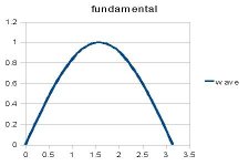
I have been thinking about how to demonstrate that the linear model of skin effect can exhibit behaviour which might appear to be non-linear when viewed in the time domain. I have come up with a spreadsheet model which shows this. The idea is to make an approximation to a square wave using a variable number of harmonics, and then show how adding up the current density gives the impression of slew rate varying the skin depth.
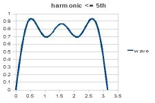
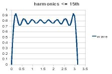
A square wave consists of all odd-order harmonics, with the nth harmonic having amplitude 1/n. I have used up to the 25th harmonic. Of course you get Gibbs' phenomena near the edges but I hope that will not detract from my argument. Near the zero crossing the fundamental and harmonics are all in phase, so the slew rate is fairly high. In the centre of the (somewhat wiggly) 'flat' top they alternate in phase so the slew rate is lower; actually, at the centre of the top the slew rate is zero as all the component waves are at a positive or negative peak. A slew-rate dependent model would presumably show uniform current density here?
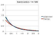
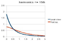
In the linear model found in textbooks, which I believe is required by the linear nature of Maxwell's equations and Ohm's Law, the skin effect penetration depends on frequency and geometry alone so there is no variation of the skin depth during the AC cycle. To find the current density for a complex waveform you have to calculate it separately for each Fourier component, and then add up the resultant effects (taking account of phase as well as amplitude). This is what I have done. I show results for fundamental only, and for up to 5th and 15th harmonics. I also have 9th and 25th, but I don't want to bore people!
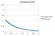
The first set of pictures show (half of) the waveform. The second set show the current density. It can be seen that around the zero crossing the current is nearer the surface. This is not because skin effect depends on slew rate, but because of the way the Fourier components add up.
Units are arbitrary. I have tried to scale/normalise the results but it is the shape of the current density curve which matters rather than the absolute values. I used a half-thickness of 3 times the skin depth at the fundamental frequency (e.g. a conductor thickness of 6 times the skin depth).
Somewhat surprisingly (at least to me) adding extra harmonics makes very little difference to the 'flat top' current density profile, although there is a hint of some flattening of the curve. However, they do make a significant difference near the zero crossing.
To sum up, I have demonstrated, in a way which satisfies me, that a purely linear frequency-dependent model of skin effect can exhibit a result which at first sight looks like a non-linear slew-rate dependent skin effect. I believe this confirms that jn and his colleague have drawn a false conclusion from the results of their time-domain modelling.
I have been thinking about how to demonstrate that the linear model of skin effect can exhibit behaviour which might appear to be non-linear when viewed in the time domain. I have come up with a spreadsheet model which shows this. The idea is to make an approximation to a square wave using a variable number of harmonics, and then show how adding up the current density gives the impression of slew rate varying the skin depth.
A square wave consists of all odd-order harmonics, with the nth harmonic having amplitude 1/n. I have used up to the 25th harmonic. Of course you get Gibbs' phenomena near the edges but I hope that will not detract from my argument. Near the zero crossing the fundamental and harmonics are all in phase, so the slew rate is fairly high. In the centre of the (somewhat wiggly) 'flat' top they alternate in phase so the slew rate is lower; actually, at the centre of the top the slew rate is zero as all the component waves are at a positive or negative peak. A slew-rate dependent model would presumably show uniform current density here?
In the linear model found in textbooks, which I believe is required by the linear nature of Maxwell's equations and Ohm's Law, the skin effect penetration depends on frequency and geometry alone so there is no variation of the skin depth during the AC cycle. To find the current density for a complex waveform you have to calculate it separately for each Fourier component, and then add up the resultant effects (taking account of phase as well as amplitude). This is what I have done. I show results for fundamental only, and for up to 5th and 15th harmonics. I also have 9th and 25th, but I don't want to bore people!
The first set of pictures show (half of) the waveform. The second set show the current density. It can be seen that around the zero crossing the current is nearer the surface. This is not because skin effect depends on slew rate, but because of the way the Fourier components add up.
Units are arbitrary. I have tried to scale/normalise the results but it is the shape of the current density curve which matters rather than the absolute values. I used a half-thickness of 3 times the skin depth at the fundamental frequency (e.g. a conductor thickness of 6 times the skin depth).
Somewhat surprisingly (at least to me) adding extra harmonics makes very little difference to the 'flat top' current density profile, although there is a hint of some flattening of the curve. However, they do make a significant difference near the zero crossing.
To sum up, I have demonstrated, in a way which satisfies me, that a purely linear frequency-dependent model of skin effect can exhibit a result which at first sight looks like a non-linear slew-rate dependent skin effect. I believe this confirms that jn and his colleague have drawn a false conclusion from the results of their time-domain modelling.
Attachments
- Status
- This old topic is closed. If you want to reopen this topic, contact a moderator using the "Report Post" button.
- Home
- Design & Build
- Parts
- Copper foil versus wax coil inductors