I did provide a detailed test method you could use to distinguish, explained the differences and similarities, so that you could determine if it made any difference in your speakers. Me, I only listen casually, without concern for the soundstage.Yes, thanks Merlin. I was refering to DF96 and JNeutron disagreeing about the finer details of proximity effect which wasn't really what was asked.
Jn
If you and your colleague are right in your interpretation of your measurements then you have a nonlinear effect from a completely linear system. Apart from being mathematically impossible, this would mean that many RF systems would suffer significant distortion without any nonlinear component being present.jneutron said:Indirectly by current slew? (I assume you meant to say slew, my I pad continuously changes words on me).
Oddly enough, when we charge an inductor at 83 amps per second for 80 seconds, we can easily measure the changed resistance from proximity effect. Straight forward, easy to do. The resistance bumps to a new, constant value during the entire ramp. When we flat-top, the resistance drops to it's DC resistance.
When we ramp down, the resistance increases during the ramp down, and remains at the higher value until zero.
The proximity based resistance increase is a direct function of the absolute value of the rate of change of the magnetic field. If you are calling the absolute value function "linear", then we are in agreement.
The EM textbooks start from Maxwell's equations. They assume that a sinusoidal source produces sinusoidal field oscillations everywhere - this seems a reasonable assumption for a linear system. It is then found that the geometry of these fields (and currents etc.) depends on frequency and material properties (also assumed linear - a good approximation in many cases), so the effective resistance depends on these too. No slew based variation in resistance is seen; just frequency dependence.
What I think you are seeing is skin and proximity effect raising resistance for the higher frequency components of your waveform, plus some effects of inductance. The net result is the appearance of slew-rate dependent resistance, but this is not what is actually happening. You are looking in the time domain, while the textbooks look in the frequency domain, but the end result must be the same: no nonlinearity, no new frequency components, just a linear filter.
Yes, thanks Merlin. I was refering to DF96 and JNeutron disagreeing about the finer details of proximity effect which wasn't really what was asked.
Well both contributing each one with his point of view. You have to decide or try by yourself.
An 80 second ramp, the start transition settles down in milliseconds, and is steady state for 80 seconds. When it flat tops, again, quick settling.If you and your colleague are right in your interpretation of your measurements then you have a nonlinear effect from a completely linear system. Apart from being mathematically impossible, this would mean that many RF systems would suffer significant distortion without any nonlinear component being present.
The EM textbooks start from Maxwell's equations. They assume that a sinusoidal source produces sinusoidal field oscillations everywhere - this seems a reasonable assumption for a linear system. It is then found that the geometry of these fields (and currents etc.) depends on frequency and material properties (also assumed linear - a good approximation in many cases), so the effective resistance depends on these too. No slew based variation in resistance is seen; just frequency dependence.
What I think you are seeing is skin and proximity effect raising resistance for the higher frequency components of your waveform, plus some effects of inductance. The net result is the appearance of slew-rate dependent resistance, but this is not what is actually happening. You are looking in the time domain, while the textbooks look in the frequency domain, but the end result must be the same: no nonlinearity, no new frequency components, just a linear filter.
Higher frequency components in an 80 second ramp? They're long gone.
My friend has to deal with even bigger challenges than this. He derives analytical solutions when the conductors are super, built on stainless tubes. The combination during ramp has eddy currents, skin effect in the supers, and persistent currents in the super that lives forever cold. What you and I are bandying about is actually quite trivial.
We agree in that all the textbooks deal with this in the frequency domain, and looking both ways must produce the same results. I've done this in the time domain for a few decades, others up to five. The best guy I know works in both, and he has abandoned the textbooks for reason.
Perhaps you should try modeling in the time domain, Roxio or Opera perhaps? They both deal well with iron, and it's easy to set the permeability to 1 for air.
As always, discussion with you is a pleasure.
Jn
An 80 second ramp is still higher frequency than DC.
We agree that time domain and frequency domain must give the same answer.
Can we agree that proximity effect and skin effect are essentially the same phenomenon, but one is a self-effect and the other is a mutual effect? I say this because most textbooks are more likely to do the full sums for skin effect, and then just mention proximity effect without going into details. I can't extrapolate from one to the other if you see them as quite different phenomena.
Agreed. but the ramp we use is in the ppm level of accuracy, and we have to watch for millivolt problems with the superconductors in the millisecond domain.An 80 second ramp is still higher frequency than DC.
Absolutely. The problem I see in all the textbook and research domain, is the assumption that for a specific frequency the current density profile during proximity effect is constant, but different for each frequency. Proximity effect and current crowding is rate of change of magnetic field dependent. Building on the assumption that for each frequency the current density profile is static means that all further analysis requires it and any statements to the contrary are argued against using an analysis that was based on assumptions. So my concern is that the initial assumptions are the problem.We agree that time domain and frequency domain must give the same answer.
Not to worry, we see both in the exact same way.Can we agree that proximity effect and skin effect are essentially the same phenomenon, but one is a self-effect and the other is a mutual effect? I say this because most textbooks are more likely to do the full sums for skin effect, and then just mention proximity effect without going into details. I can't extrapolate from one to the other if you see them as quite different phenomena.
A pleasure as always.
jn
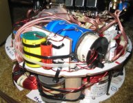
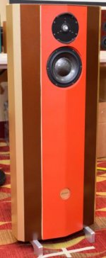
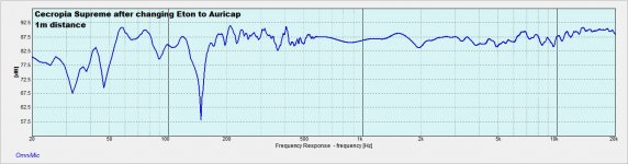
I did a subjective test on coils a little over a year ago. My Cecropia Supreme project was my test-bed. DCR was matched with a resistor in the tweeter shunt, and all were similar in the woofer sector except the P-core. I used what follows...
Tweeter:
Litz14
Foil12
Foil16
WaxFoil16
AirCore14
AirCore22
Woofer:
AirCore14
Icore18
P-Core15
Foil14
Litz14
My take on all of this is that the foils pretty much all sound similar to each other, regardless of AWG. This might change had I not matched the DCR. P-Cores sound like poop by comparison to everything else I tried; loss of detail and just plain bad. I-cores have a bit of emphasis in the midbass region, that is pleasant to many.
I even did a somewhat blind test, letting the crowd unknowlingly select what they liked best. Litz on the tweeter and Icore on the woofer came out on top. That slamming midbass helped the I-core there. The litz on the tweeter provided a bit of a BBC dip, and I'm still not sure why. The Air22 was also plagued by this abnormality, but did not sound as good.
I even did some measurements, and have my listening preference being Litz14 on the woofer and Air14 on the tweeter. The warmth in bass and loss of clean mids did not agree with me like the spur of the moment crowd exercise.
FWIW, the foils did not sound as good/open and detailed as the Air or Litz coils.
So- I would not use Litz on tweeters, likely due to the inherent capacitance of the component. On the woofer, it was a more open and detailed best choice.
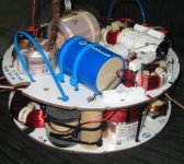
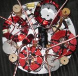
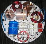
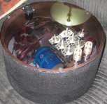
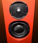
Be advised there were 2 versions of this journey. I used the CAW634 initially for the woofer, and the Tlabs N26MGR-G tweeter, later switching out the CAW for the TSCW636. My sentiments agree in both iterations about what I liked best. The CAW version info has been used here to show the entire circuit setup, as well as coil placement photos. It took me 6 months to lay this out and not get coil interactions, and works by switching out both coils in the driver circuit at the same time, tweeter and woofer are independent.
Later, and I hope this helps you make your decisions,
Wolf
Tweeter:
Litz14
Foil12
Foil16
WaxFoil16
AirCore14
AirCore22
Woofer:
AirCore14
Icore18
P-Core15
Foil14
Litz14
My take on all of this is that the foils pretty much all sound similar to each other, regardless of AWG. This might change had I not matched the DCR. P-Cores sound like poop by comparison to everything else I tried; loss of detail and just plain bad. I-cores have a bit of emphasis in the midbass region, that is pleasant to many.
I even did a somewhat blind test, letting the crowd unknowlingly select what they liked best. Litz on the tweeter and Icore on the woofer came out on top. That slamming midbass helped the I-core there. The litz on the tweeter provided a bit of a BBC dip, and I'm still not sure why. The Air22 was also plagued by this abnormality, but did not sound as good.
I even did some measurements, and have my listening preference being Litz14 on the woofer and Air14 on the tweeter. The warmth in bass and loss of clean mids did not agree with me like the spur of the moment crowd exercise.
FWIW, the foils did not sound as good/open and detailed as the Air or Litz coils.
So- I would not use Litz on tweeters, likely due to the inherent capacitance of the component. On the woofer, it was a more open and detailed best choice.
Be advised there were 2 versions of this journey. I used the CAW634 initially for the woofer, and the Tlabs N26MGR-G tweeter, later switching out the CAW for the TSCW636. My sentiments agree in both iterations about what I liked best. The CAW version info has been used here to show the entire circuit setup, as well as coil placement photos. It took me 6 months to lay this out and not get coil interactions, and works by switching out both coils in the driver circuit at the same time, tweeter and woofer are independent.
Later, and I hope this helps you make your decisions,
Wolf
Attachments
-
 IMG_3488CROP.jpg39.9 KB · Views: 304
 -
 IMG_3481CROP.jpg129.2 KB · Views: 299
 -
 IMG_3480CROP.jpg95.6 KB · Views: 285
 -
 IMG_3524.JPG60.9 KB · Views: 294
 -
 IMG_3801.JPG76.3 KB · Views: 275
 -
 Closeup1.jpg53.4 KB · Views: 129
 -
 Closeup2.jpg19.3 KB · Views: 91
 -
 SupremeVerify.jpg139.1 KB · Views: 87
 -
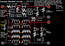 Cecropia Uberfahrt Circuit Sim3.png200.2 KB · Views: 116
 -
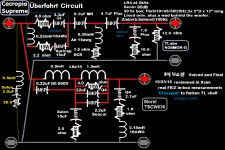 Cecropia Supreme Uberfahrt Circuit Measured&Voiced.png162.1 KB · Views: 119
Last edited:

Wolf_teeth,
What is an Icore and what is a P-core? Does that indicate the shape of the iron or ferrite?
And thanks for your take on the parts..
Jn
I-core is a steel-laminate rectangular slab of silicon-steel.
P-core is a sintered permite core with ferrite slabs on either end of the cylindrical coil. Jantzen makes them.
ThetaII-
No coupling that I could tell. Measurements were not affected. As I said- the foils all sounded the same to me, and lacked the resolution of the air-cores.
Later, and you're welcome!
Wolf
OK.jneutron said:Not to worry, we see both in the exact same way.
The usual textbook assumption is that with a sinusoidal source (whether current or incoming field) the fields everywhere will have a sinusoidal variation at that same frequency, and then the solution separates into a geometric term (constant with time) multiplied by a sine. You are saying that that this is an incorrect way to find a solution, if I understand you correctly. You say that the geometric term is time-dependent, and varies like the absolute value of the slew rate. If so, then this variation at twice the source frequency would give rise to sum and difference products so we would get some field (and current?) variations at three times the source frequency.
How can a linear system (Maxwell plus Ohm) produce a nonlinear result? There is nothing in the equations to generate harmonics. The basic maths of this situation says no.
Now let's do a thought experiment. At lower RF frequencies the main loss mechanism in a transmission line is conductor resistance, and this will be made worse by skin/proximity effect. If your understanding is correct then this loss will vary somewhat through the RF cycle, as the skin effect varies according to slew rate. Again there will be generation of harmonics. As far as I am aware this phenomenon has never been seen: a non-faulty cable used well within its power handling range nevertheless producing signal distortion. The magnitude of any such effect would be commensurate with the cable loss at that frequency (a bit smaller, but not hugely so) so ought to be fairly obvious.
1. Lorentz force. When I power a solenoid, hoop stress is outward. From zero positive, the hoop expands. From zero negative, the hoop expands. Some of our stuff has forces in excess of 5 KPSI, Niobium tin up to 10Kpsi. HTS, lord only knows, we're past 22 tesla now.
2. Zip cable . When the current is flowing, the wires are being pushed apart. With sinusoidal excitation, the force on the conductors are consistent with a full wave rectified signal.
3. magnetostrictive. I run ultrasonic welding equipment that uses a pure nickel laminated stack (no hysteresis). If I use an ac excitation field, the stack will shrink twice per electrical cycle. For me to properly use them, I have to introduce a biasing dc field such that the stack never sees a zero crossing. Transformers typically buzz at twice frequency, and copper coils in same also vibrate at twice frequency.
4. Coiled inductor. when I drive a coil inductor with a current slew in the positive direction, the current centroid drives inward. This INCREASES the conductor resistance (POSITIVE) as less copper is involved in the current conduction. When I drive it with a current slew in the negative direction, the current centroid drives inward again, resulting in a POSITIVE resistance increase. In other words, the current centroid pulls toward the center of the coil regardless of the direction of the rate of change of the current. The resultant resistance increases in BOTH directions. Zip conductors do the exact same thing, centroids pull in based on dI/dt...but I'd never expect sota instrumentation to be able to measure that.
5. coiled inductor: When proximity effect occurs, the current centroids pull in, so the effective radius of the inductor decreases. This causes a net change of the actual inductance (defined as the relationship between current into a system and the total energy stored E = 1/2 L I^2). If I ramp current into an inductor, the actual inductance changes at the start, and at the end of the ramp, the inductance recovers to it's DC value. If I change the sign of the current direction, the inductor does the EXACT same thing.
Every single one of these effects occur as a result of the absolute magnitude of the driving force, polarity independent.
jn
Last edited:
1, 2 and 3 are changes of geometry and I don't dispute that these would cause distortion. I thought we were discussing the ideal case where the geometry is fixed?
4 and 5 I need to think about. If the geometry is fixed (i.e. the conductors do not move) then I still cannot see how a set of linear equations can give rise to a non-linear solution. Your description of 4 and 5 of course assumes that your understanding is correct and higher slew rate means more sideways displacement of current. This of course is the nub if the argument. I would expect to see exactly the same spatial distribution of current if all currents were halved or doubled; you would expect to see a different distribution, if I understand you correctly.
4 and 5 I need to think about. If the geometry is fixed (i.e. the conductors do not move) then I still cannot see how a set of linear equations can give rise to a non-linear solution. Your description of 4 and 5 of course assumes that your understanding is correct and higher slew rate means more sideways displacement of current. This of course is the nub if the argument. I would expect to see exactly the same spatial distribution of current if all currents were halved or doubled; you would expect to see a different distribution, if I understand you correctly.
The displacement of centroids as a consequence of dB/dt in wires and coils is not my understanding, it is known and understood throughout the world of physics and engineering. It is a basic tenet within EMC, if you recall current tends to take the path of least reactance. In zip cable, as the rate of change of current increases, the current tends to concentrate closer to the othe return current. In the outside world, the tendency is to approximate the response using the frequency domain, characterizing it frequency by frequency. Sullivan of Dartmouth has great online content in this regard. However, he also has great drawings of what current in a wire does as a consequence of dB/dt. I work In the time domain because typically my conductors have infinite conductivity, skin effect, and proximity effect. But the metals used within our constructs play a big role, as copper and aluminum increase conductivity cryogenically and cannot be ignored for some rate. Stainless on the other hand, has a stable resistivity with temp. All materials (with the exception of helium) lose almost all of their heat capacity below 50K, so eddy currents in all the materials with the generated heat, and that is a big concern for quench issues. The bucking magnetic fields of the eddies give us huge concerns for field quality. Accelerator magnets typically need to ramp, and proximity effects (current centroid shift) can compromise the particle beam. My specialty involves making supercon magnets that have a non metal compression structure, removing proximity effects and eddy currents from the mix.
Since we work time domain, there is no desire by the guys to convert to frequency domain, we need exact field in time. SMPS guys on the other hand, are more concerned with dissipation and parasitics, so while they understand the physics, they are concerned about efficiency.
We cannot dissipate at all, 1 watt at 4.5K is 1 kilowatt of refrigeration, 2kw at 1.8K.
Jn Ps. Your last sentence confused me, I assume you meant same freq different amplitude. At higher amplitudes constant frequency, I would expect identical distribution just scaled. As you and I certainly expect, history HAS to play a significant role, this is where the bridge to frequency domain lies.
Last edited:
As I said- the foils all sounded the same to me, and lacked the resolution of the air-cores.
The foils are also air-cored, right? Perhaps you meant the foils were inferior to the round crossection wires. Please clarify.
Here are some measurements that shows that foil coils have better damping:
Spulen und Klang
Runddraht Spulen
Regards,
Danny
Spulen und Klang
Runddraht Spulen
Regards,
Danny
Let me check that you are saying what I think you are saying: take a given scenario A (geometry, currents etc.) then double the currents to get B. This means double the ramp rate (but for the same time period), double the steady state current at the end of the ramp etc. You expect to see double the current at every position in the conductor? If point X has three times the current of point Y in scenario A, then point X also has three times the current of point Y in scenario B - just that now both currents are twice as big.jneutron said:At higher amplitudes constant frequency, I would expect identical distribution just scaled.
The foils are also air-cored, right? Perhaps you meant the foils were inferior to the round crossection wires. Please clarify.
I thought that was pretty easy to dissect, meaning foils sound less detailed than the round or litz (litz = woofer only). You read as I meant it.
Wolf
- Status
- This old topic is closed. If you want to reopen this topic, contact a moderator using the "Report Post" button.
- Home
- Design & Build
- Parts
- Copper foil versus wax coil inductors