Ok I know that sounds like a silly question, but is it?
Some high quality film caps are marked with an "In" and "Out" lead marked on which lead is connected to the inner or outer part of the cap.
and while I was looking as some foil inductors It dawned on me that maybe they have a "preferred" direction related to signal flow as well?? Would we want the "In" to enter from the inside of the inductor and exit out the outer part? or the reverse?
ZC <---over thinking things once again!
Sure, every inductor has a polarity. For audio, I doubt it carries any meaning other than the interaction between coils in proximity to one another. The fields can buck or boost with one another with the same excitation. Again with music content with its various phase shifts of sine waves, I doubt it is of any practical effect- just keep spacing and orientation per the recommendation of other threads.
Caps are marked so that the outer can be connected to the lower impedance end in order to minimise electrostatic pickup. In many cases it doesn't matter anyway. A similar effect might possibly happen with an inductor.
Inductors also have a real polarity as, for example, a solenoid can be right or left-handed. This changes the polarity of induced voltages from elsewhere, and the polarity of the external magnetic field. Swapping ends does not change this (think about it!).
Inductors also have a real polarity as, for example, a solenoid can be right or left-handed. This changes the polarity of induced voltages from elsewhere, and the polarity of the external magnetic field. Swapping ends does not change this (think about it!).
Current inductors do have polarity issues.
Imagine a spiral copper wire and two free electrons are put at the center tip of the spiral, the two electrons will expel each other and try to keep away from each other as far as possible, finally they will stay at the most outer ring of the spiral, apart from each other at the two most distant points in the spiral they can find.
Since it is the free electrons that carry the current in copper wires, that means the negative electrons have a tendency to flow from inner round to outer in a conventional spiral coil, which means it is easier for the positive current to flow from the outer round to the inner. So which side of the coil (inner or outer) would you call it the positive?
Most music we heard are asymmetrical signals, piano strikes a string so its first wave of sound has a positive sound pressure to our ears, drums are the same. Human voice is generated by pushing air out of lungs, that is also asymmetrical and has a positive sound pressure for the first wave. So you see it must be carefully handled from the picking-up mic to the speaker driver, any mistake would make the first output sound wave become negative sound pressure, and that is definitely not fidelity. And asymmetry is very important for us to distinguish a sound, and so is asymmetrical distortions. Yet some people cannot hear the difference but some people can.
Now back to the polarity of the coils, as we can see now an inductor do have polarity issues as long as it is wound with asymmetrical inner and outer rounds. Unfortunately the most expensive foil coils have the most severe inner and outer round problems because they are perfect spiral coils. Multi-layer wire wound coils also have asymmetrical inner and outer round problems. Iron core coils have fewer rounds and sometimes they have only one layer of wires that makes them polarity-free, but they have another severe issue of hysteresis to overcome.
What would it be like for a coil to have polarity that generates asymmetrical distortions? I don't know. But here is a video showing a person messing around a drum signal with various asymmetrical distortions, it might give you an idea about what it would sound like:
YouTube
So I would say, in a microscopic view, the coils currently available in the market all have polarity issues as long as they are asymmetrically multi-layered, and asymmetrical distortions are definitely there.
I understand that the truth is that most people cannot hear absolute phase with most music. A minority of people can hear absolute phase on some music.DBruce said:Yet some people cannot hear the difference but some people can.
The talk about electrons and coils is too unclear to comment on in detail, but I strongly suspect it to be bunkum.
It all depends on impedance. Say the outside of the component has 0.1pF stray capacitance to some mains wiring that's been routed close to the pcb. That means the capacitive pickup will be 7.5nA (for 240V 50Hz).
In a 1k impedance circuit that's 7.5µV, in a 100k impedance circuit its 0.75mV. The latter is likely to appear as obvious hum in a preamp circuit. The former is only going to be an issue for something like a sensitive microphone or phono preamp.
This is one of the reasons for using low impedances in solid state circuitry, the other being less Johnson noise and less magnification of current noise.
But its rare to see an inductor in an audio signal path these days, so its rather a moot point. For capacitors in filter circuits it is a valid concern at times, but most people ignore it.
Ok I know that sounds like a silly question, but is it?
Some high quality film caps are marked with an "In" and "Out" lead marked on which lead is connected to the inner or outer part of the cap.
and while I was looking as some foil inductors It dawned on me that maybe they have a "preferred" direction related to signal flow as well?? Would we want the "In" to enter from the inside of the inductor and exit out the outer part? or the reverse?
ZC <---over thinking things once again!
For capacitors, I would take the same theory as in my previous post, i.e. for a spiral type capacitor, it is harder to gather electrons at the inner film than at the outer film, if electrons can actually travel in capacitors, they would flee from the inner film to the outer more easily.
So if one needs a capacitor with lower leakage, he can connect the outer film to the more negative side and make it harder for electrons to travel or leak between films.
Likewise, if a flyback transformer has multi-layer windings, to connect the outer layer to the positive source would be a logical selection.
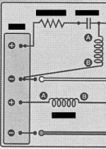
My previous discussion is mainly focused on the crossover inductors which is bulky and the current is high. Some people have been complaining that when they switch the two leads of their inductors in the crossover circuit, they can hear the speaker sound is different. I was just trying to bring out a possible theory for it, i.e. inductor polarity might be causing asymmetrical distortions.
Or maybe there are some other better explanations for this.
Inductors (mainly with higher frequencies) behave better when the inner turns are liver than exterior ones, this way the electric field near the inductor is much less, while magnetic field is unaffected, because lower RF potential turns act as a shield for E. I generally manufacture my own coils in such a way.
You will have to run that one past me again. The leakage current in a film capacitor (i.e. symmetric non-polar dielectric) will depend on the DC polarity of the outer foil?DBruce said:So if one needs a capacitor with lower leakage, he can connect the outer film to the more negative side and make it harder for electrons to travel or leak between films.
In addition to all of the above, inductors can have an absolute (DC) polarity if they are of the cored variety: if the core is magnetized, the amplitude inductance will be different for the two polarities (which doesn't mean it could be used for rectification though).
This property was abundantly used in the CRT display era for various corrections: a small, generally adjustable magnet was attached to the ferrite core.
Note that even soft ferrites can retain a small remanent field
This property was abundantly used in the CRT display era for various corrections: a small, generally adjustable magnet was attached to the ferrite core.
Note that even soft ferrites can retain a small remanent field
Attachments
That makes no sense to me, the issue is that the outer film has more stray capacitance to the surroundings than the inner film. Nothing whatsoever to do with leakage which is a property of the dielectric film.For capacitors, I would take the same theory as in my previous post, i.e. for a spiral type capacitor, it is harder to gather electrons at the inner film than at the outer film, if electrons can actually travel in capacitors, they would flee from the inner film to the outer more easily.
So if one needs a capacitor with lower leakage, he can connect the outer film to the more negative side and make it harder for electrons to travel or leak between films.
As normally occurs that the capacitance of the coupling cap is several order of magnitude larger than the stray capacitance, the cap shorts both ends at the frequencies in which strays are relevant.That makes no sense to me, the issue is that the outer film has more stray capacitance to the surroundings than the inner film. Nothing whatsoever to do with leakage which is a property of the dielectric film.
The figure below shows what I meant, though you might think it's trivial.
Electrons stay at the inner film have higher potential to each other. They have a tendency to travel to the outer film.
Note: if you cannot see the figure, try right-click and open in new window. Sorry for this. It took me some time to share the figure.
Electrons stay at the inner film have higher potential to each other. They have a tendency to travel to the outer film.
An externally hosted image should be here but it was not working when we last tested it.
Note: if you cannot see the figure, try right-click and open in new window. Sorry for this. It took me some time to share the figure.
Last edited:
- Status
- This old topic is closed. If you want to reopen this topic, contact a moderator using the "Report Post" button.
- Home
- Design & Build
- Parts
- Inductor Polarity??