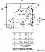
there is an old Motorola application note that used MJ2501 and Mj3001. this is one version that used lower power Darlington's. I cant find the original application note for the MJ2501 3001. I made several versions from 35 watts to 100watts per channel and sold to friends in the early 70's. One of the amplifiers is still working!
i guess that those emitter resistors could heat up very easily. 10A through a 0.22 ohm resistor make 22 Watt to be dissipated ?
The problem is that it is a thin film resistor. You will NEVER get one of those to handle as much short term overload as a wire wound resistor. It will blow before the bond wire to the die does.
there is an old Motorola application note that used MJ2501 and Mj3001. this is one version that used lower power Darlington's. I cant find the original application note for the MJ2501 3001. I made several versions from 35 watts to 100watts per channel and sold to friends in the early 70's. One of the amplifiers is still working!
100 watts per channel at 4 ohms isn’t all that big, and the 150 to 200 watt TO3’s, darlington or not, will handle that just fine. The biggest limitations of those old power darlingtons is the 80 volt supply limit. 100 at 4 ohms is all you’ll get unless you use a 2kVA transformer to get 2% regulation. 100 at 8 ain’t happening, just because you need more voltage to get there than those 80 or even 100 volt transistors will handle.
View attachment 896688
i forgot the image
Hi Thank you very much indeed. In the Motorola parts the resistors are outside the chip ... that is a very good thing i understand

OTOH, 10 A RMS emitter current per device isn't that probable. That surely would kill the device/die itself, due to SOAR infringement.
Best regards!
The dies will easily handle 300 or more watts for 10 milliseconds. The resistor won’t handle 10 amps that long. SOA infringements happen all the time for less than one audio cycle durations in most consumer equipment. Now if you put six units in parallel to stay inside the temp derated SOA for DC, during the entire dynamic load line (ellipse) you probably won’t hurt the resistor either. But no one ever does. What you see is one pair of output devices on some +/-55v (unloaded) supply. It will take it if you’re very very gentle with it. But that’s it. The silicon die itself might take a momentary short, with some current limiting mechanism kicking in fairly quickly. But not quickly enough to protect the fuse (resistor).
It will however, prevent the PCB from going up in flames. But you’re stuck replacing a pair of transistors. Fine and dandy if you have some on hand. Take that to a shop and you’re out $200.
The problem is that it is a thin film resistor. You will NEVER get one of those to handle as much short term overload as a wire wound resistor. It will blow before the bond wire to the die does.
OTOH, 10 A RMS emitter current per device isn't that probable. That surely would kill the device/die itself, due to SOAR infringement.
Best regards!
Hi thanks for the very helpful advice. I do not know if a look at the sap16 safe operating area can tell anything I am attaching it
Attachments
- Status
- This old topic is closed. If you want to reopen this topic, contact a moderator using the "Report Post" button.
- Home
- Design & Build
- Parts
- Can I build up these Darlington transistor if I use two BJT transistor ?

