Yeah, I got surprised too...
However, Microchip aren't offering samples since a long time.
(The fact that Atmel's AVR microcontroller market's share increasing quickly with time is probably one of the reason motivating Microchip sample program...)
I'm very impatient to try my hand on DSPic but it seems that they're not available yet... Microchip are announcing them for several months and still nothing..
Ok I think I will mostly use 16F84 and 16F877... I found this programmer called JDM, it's easy to build and can program
these two PIC's.
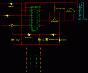
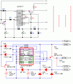
I joined two schematics in one picture to make things easier. They are the same, but I can't think a way to join them in one to build the circuit in a prototype board, with two rows of sockets 40 and 18 pins, one inside other so I dont have to use adapters.
Does anyone can help me?
these two PIC's.
I joined two schematics in one picture to make things easier. They are the same, but I can't think a way to join them in one to build the circuit in a prototype board, with two rows of sockets 40 and 18 pins, one inside other so I dont have to use adapters.
Does anyone can help me?
Attachments
future said:Ok I think I will mostly use 16F84 and 16F877... I found this programmer called JDM, it's easy to build and can program
these two PIC's.
I joined two schematics in one picture to make things easier. They are the same, but I can't think a way to join them in one to build the circuit in a prototype board, with two rows of sockets 40 and 18 pins, one inside other so I dont have to use adapters.
Does anyone can help me?
It's easier that you think - to programme a PIC, you just need to connect GND, +5V, RB6, RB7 and /MCLR
Build one programmer circuit, and connect these 5 signals to the appropriate pins on the 18 and 40 pin sockets.
An important hint here: While this isn't so bad with the smaller 16F84, you'll soon get really fed up with removing the 16F877 from your circuit, inserting it in your programmer, then replacing it in the circuit. You'll probably bend pins or wear your socket out. So, consider making an adaptor lead like I did. You just need to put a 4 or 5 pin Molex connector on your board, then plug it in to your test system when you want to programme the PIC...
The other end of the adaptor lead is soldered onto an IC socket that fits into my programmer. Easy!
An externally hosted image should be here but it was not working when we last tested it.
This adaptor lead doesn't bother with +5V - the 16F877 gets its power from the rest of the system... The cable is just a standard internal CD-ROM audio lead, complete with neat heatshrinking and 4-way connector - recycling rules
sockets
I find a ZIP socket is helpful for programming -- this is what Microchip uses on the little programmer PICStart Plus -- also, if you are going to do a lot of prototyping it's a good idea to use a carrier for the PIC -- as the pins will bend and break after a while -- you can use a "machined" socket for this. You can also mount an SMT PIC or AVR on an adapter board -- sometimes the SMT versions are dirt cheap.
of course, one of the reasons folks use STAMPS and BX24's is that you can program these devices on the fly.
future, before you build this one, please use a DMM and check the voltages at the PC´s serial port. It may work with 16F8xx in case voltage from PC is high enough, but cause problems with 16F84 type. The voltage from PCs serial port spreads very wide, and if it is not enough PIC will not go in programming mode. Programmers with external powers supply will be safer.
this diagramm shows required programming voltage :
http://www.sprut.de/electronic/pic/brenner/vpp.htm
this works with different external power supplys an parallel port
http://www.sprut.de/electronic/pic/projekte/brenner5/br5_sch.gif
and this i would like to build, but PCB is not so easy to make. If you want to make it i can send you the requred Pic, (i ´m strongly interested in making a PCB for me):
http://www.piclist.com/images/com/multimania/www/http/silicium31/Electronique/PIC/free_icd_en.htm
Using ZIF sockets is a nice idea but you'll need one on your programmer and one in your target board (your prototype).
40 pins ZIF sockets aren't cheap.
Using ICSP (In-Circuit-Serial-Programming), you only need those pins : GND, +5V, RB6, RB7 and /MCLR. This way, you don't need to remove and insert your chip all the time.
As you probably know, Microchip ICD schematics are available on their website so why not use them ?
i found on the following site a complete ICD projet with PCB, instructions etc... You don't want to miss that link.
Here's the original version of the previous link with color pictures
http://membres.lycos.fr/silicium31/Electronique/PIC/free_icd.htm
Take a look, you won't be disapointed.
Regards,
comments?
been surfing:
it seem like there is a hundred variants of each parallel port/serial port PIC programmer out there.
I suspect people could not understand each others diode-cap-zener combos to create the required +5 and +12
most seem to be PC port dependant
the real RS232 spec on a serial port is huge 3-25v, thus the variants
If you have a desktop PC keep in mind these voltages ara available on a HD connector. I am leaning towards designs with an external (HD?) power - seems much more reliable.
low voltage programming looks like you give up a pin, which seems restrictive to me
if I was going to buy one the picflash USB or clone seems to have a future
if i was building for simplicity - the ludipipo w external supply is like 3 resistors. period.
ludipipo and jdm and jmb and c84 all seem to use the same rs232 pin assignments.
ic prog seems like a strong programmer supports most hardware , lets you tweak
comments?
edit-I see lots of complaints about the el-cheapo (predko), cuz there are so many or the architecture?
- Status
- This old topic is closed. If you want to reopen this topic, contact a moderator using the "Report Post" button.
- Home
- Design & Build
- Parts
- PIC programming


