Hi Andrew,
That question got me thinking, does this help
http://books.google.co.uk/books?id=...=X&oi=book_result&resnum=7&ct=result#PPA35,M1
That question got me thinking, does this help
http://books.google.co.uk/books?id=...=X&oi=book_result&resnum=7&ct=result#PPA35,M1
here is datasheet from manufacturer www.linearsystems.com
http://www.linearsystems.com/datasheets/LSK170.pdf
http://www.linearsystems.com/datasheets/LSK170.pdf
AndrewT said:thanks,
Mooly,
can the Yfs test measurement be done at DC? instead of at RF?
When testing Idss, the Vgs =0V and Vds=10V with RL=100r.
Then Yfs=infinity, which is plainly ridiculous.
I have referenced Erno's 1999 article on JFET's with his testing methodology -- nice test setup:
http://www.borbelyaudio.com/adobe/ae599bor.pdf
Andrew, this is something I have never measured. I don't know is the honest answer ! I suspect there is no one correct answer in that the result depends on the particular application, and that application depends on the correct choice of FET. Sort of chicken and egg thing. Sorry.
Hi,
For a given technology, there is a direct correlation between gfs, Idss and Vgs off.
Here is an example taken from the BF256 datasheet.
It's just a matter of finding the right parameters to put into the equation of the device. It can probably be found on the web.
Otherwise, you can measure gfs at low frequencies; a static, DC measurment makes no sense however.
Attachments
Thanks Jack.jackinnj said:
I have referenced Erno's 1999 article on JFET's with his testing methodology -- nice test setup:
http://www.borbelyaudio.com/adobe/ae599bor.pdf
If mhos is the inverse of ohms then R=V/I becomes Mho=I/V or if the curve is not straight then Mho=deltaI/deltaV.
However Borbely states Mho=2*Idss/Pinch off voltage.
Why is there a factor of 2 times in Borbely's formula?
and if Borbely is close to right and both terms in the formula are DC derived, then why is Yfs @ DC a nonsense?
AndrewT said:
Thanks Jack.
If mhos is the inverse of ohms then R=V/I becomes Mho=I/V or if the curve is not straight then Mho=deltaI/deltaV.
However Borbely states Mho=2*Idss/Pinch off voltage.
Why is there a factor of 2 times in Borbely's formula?
and if Borbely is close to right and both terms in the formula are DC derived, then why is Yfs @ DC a nonsense?
Id = Idss * [1-Vgs/Vp]^2
gm = d I (d)/ d V (gs)
so when you differentiate, the 2 goes on the outside.
I'm wondering what I am missing here?
The LSK170 is Linear's copy of Toshiba's 2SK170, so I would suggest to use the transconductance plot of the 2SK170*. As the transconductance flattens for values above say 10mA I would expect maybe 55-60mS at 20mA IDSS.
What to use it for?
Well such high currents set a strict limit on voltage to stay within power dissipation. Generally half of max power dissipation is considered to be the safe limit, so you can use the jfet with about 10V (20mA, 200mW) and even less -nice 5V- for your 40mA parts.
Noise is also better with less VDS, but 5V is in my eyes a bit away from a usefull VDS - as linearity is concerned.
So you can heavily degenerate it (to get the current down), generating more noise in the process - not so nice for a low-noise part.
However there's one exception from above statement and that is usage in a LTP where you feed the jfet with a constant current source. Doing this with say 1mA you loose much transconductance, but get a higher VDS.
It's all about compromises, as usual.
I'm sorry that I know of no better use
Have fun, Hannes
*otherwise building a transconductance rig should not be hard, right?
It turns out that my batch of 200 LSK170c had 89 that were out of specification ranging in Idss from 20.5mA to 28.9mA.
If I can prove that these low noise devices have a Yfs of~40mS then they are close equivalents of 2sk369V. These are supposed to be near ideal for low voltage amplification duty eg. MC pre stage.
It looks like using Yfs=2 * Idss / Vpinch off
will give Yfs~40mS if Vpinch off is around 1V. Testing Wednesday for this.
An alternative for higher IDSS JFET
for example in CCS, current sources
is Supertex Depletion MOSFET.
Using only 1 resistor + MOS, you have one current source.
Also I think, but I am not sure, these mosfets are less sensitive
to AC Voltage variatons across the CCS.
And so possibly not need and CASCODING like jfets.
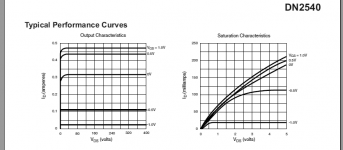
DN2535 and DN2540 comes in TO-92, 1 Watt
and TO-220, 15 Watt
DN2540, runs like 320 mA, at VGS 0 Volt
And so can be use as simple '1 Resistor Current Source': 0 - 300 mA
Litterature:
http://www.supertex.com/pdf/misc/d_mode_mosfets_SG_device.pdf
http://www.supertex.com/mosfet_selection_tool.html
for example in CCS, current sources
is Supertex Depletion MOSFET.
Using only 1 resistor + MOS, you have one current source.
Also I think, but I am not sure, these mosfets are less sensitive
to AC Voltage variatons across the CCS.
And so possibly not need and CASCODING like jfets.
DN2535 and DN2540 comes in TO-92, 1 Watt
and TO-220, 15 Watt
DN2540, runs like 320 mA, at VGS 0 Volt
And so can be use as simple '1 Resistor Current Source': 0 - 300 mA
Litterature:
http://www.supertex.com/pdf/misc/d_mode_mosfets_SG_device.pdf
http://www.supertex.com/mosfet_selection_tool.html
Attachments
2SK369 is no wonder part, you can parallel 2x 2SK170 to get identical specs (if matched nicely).
I'm reluctant to trust parts outside spec.
Have fun, Hannes
EDIT: depletion mosfets are also a nice alternative, but need quite some bias for linearity. But I guess that was not the question.
EDIT2: Andrew, you can easily measure transconductance directly. You just need 2 different bias voltages and an amperemeter. If the 2 bias voltages are sufficiently close to eachother that's a perfectly nice approximation (since one linearises a non-linear curve).
AndrewT said:If mhos is the inverse of ohms then R=V/I becomes Mho=I/V or if the curve is not straight then Mho=deltaI/deltaV.
sounds like you are confirming my earlier post.h_a said:you can easily measure transconductance directly. You just need 2 different bias voltages and an amperemeter. If the 2 bias voltages are sufficiently close to each other that's a perfectly nice approximation (since one linearises a non-linear curve).
Hi Mooly,
that's useful relationship.
Id, I was already aware of.
But noise resistance proportional to 1/Gfs.
and leads directly to Low Vg and high Id in turn requiring high Idss and high Yfs as a pre-requisite for low noise.
This kind of explains why k369 is useful for low noise amps and why k170/j74 & k389/j109 are often used for front end amplification duty.
I think I should be trying these High Idss FETs in the front end of a test gain stage to see if I can detect a (possibly) quieter front end.
- Status
- This old topic is closed. If you want to reopen this topic, contact a moderator using the "Report Post" button.
- Home
- Design & Build
- Parts
- High Idss jFETs