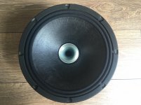
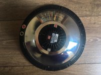
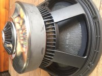
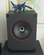
I have built closed box with BMS 10C262 recently. The box itself is trivial, though a bit oversized for this driver (35l). I would like to post some measurements for those interested in BMS coaxial speakers. Speaker is used for midbass and high frequency duties. It is sitting on top of vented enclosure containing 18Sound 18NLW4100.
Driver: BMS 10C262, 8Ohm
Box: closed, 35l
Crossover: active, Minidsp, 150Hz/1300Hz
Datasheet: http://www.bmsspeakers.com/fileadmin/bms-data/product_data_2019/bms_10c262_datasheet.pdf
The frequency response on official product sheet did not look very nice. I needed a point source and decided to try it anyway. I am happy with the result. It can be crossed nicely and with active DSP it is easy to correct some FR flaws. I replaced Beyma 10G40 + CP-380_M + TD-194 with this BMS build and though I loved Beymas, especially in HF region, I would not go back.
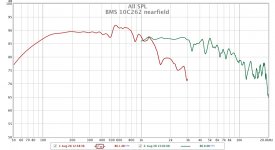
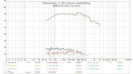
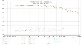
Here is measured raw FR/THD of driver after about 30 hours burn-in period.
Driver: BMS 10C262, 8Ohm
Box: closed, 35l
Crossover: active, Minidsp, 150Hz/1300Hz
Datasheet: http://www.bmsspeakers.com/fileadmin/bms-data/product_data_2019/bms_10c262_datasheet.pdf
The frequency response on official product sheet did not look very nice. I needed a point source and decided to try it anyway. I am happy with the result. It can be crossed nicely and with active DSP it is easy to correct some FR flaws. I replaced Beyma 10G40 + CP-380_M + TD-194 with this BMS build and though I loved Beymas, especially in HF region, I would not go back.
Here is measured raw FR/THD of driver after about 30 hours burn-in period.
Attachments
Thanks.
To ErnieM: You are right, off-axis measurement should be done. I will do it during coming weekend.
To pelanj: I got both drivers from TLHP (Boutique Haut-parleurs & Audio DIY). Quick delivery, no problems, transportation costs are of course significant. Initially I wanted 8+16Ohm for BMS, but got just 8+8Ohms due to long lead time.
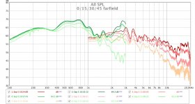
This is on/off axis measurement. Off axis measurement was taken in 15, 30 and 45 degree. The lighter the colour on picture, the bigger angle. Mic was placed 0.8m from driver at all times. Just ignore please data below 200-300Hz, because those are more valid on first set of measurements (nearfield). All measurements were windowed - 4.5ms for cone driver, 3.5ms for compression driver. Note please that measurement for cone driver and compression driver were taken with different voltage applied. Compression driver is much more sensitive of course.
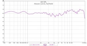
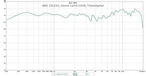
Just to give you a picture of drivers behaviour when crossed over, there is also a "fullrange" measurement. It is one of the house curves, modelled approx. according to Fletcher Munson for 80dB, crossover freq. is 1300Hz, slope BW36, 1/24 smoothing, measured from 0.8m distance.
Just to give you a picture of drivers behaviour when crossed over, there is also a "fullrange" measurement. It is one of the house curves, modelled approx. according to Fletcher Munson for 80dB, crossover freq. is 1300Hz, slope BW36, 1/24 smoothing, measured from 0.8m distance.
Attachments
Last edited:
I estimated, that there is timing misalignment between cone and compression driver, just by looking at physical dimensions. I have compensated it using minidsp, but I did not measure it exactly. I will try to measure it the next weekend, maybe my estimate was wrong. I am curious too...
Hi Mario222,
Thank you!
Glad it raised interest rather than annoyment.
Measuring this kind of thing can be tricky as it depend from emmission point which is not easily defined on the membrane of cone driver and which is frequency dependent ( it moves along the depth of cone with freq).
I don't know if you are used to that kind of measurements so here is some possible alternative method:
Finding the Relative Acoustic Offset in PCD.pdf - Box
Time-Alignment
Both share same methodology. Remember that in a coax you delay the direct radiator rather than the tweeter in conventional layout, it should reduce headache ( it did for me).
Another approach:
https://www.diyaudio.com/forums/multi-way/370287-neat-delay-phase-polarity-xover.html#post6596749
A step resp help validate outcome, not really to set it up imho. It is a bit more sofisticated and can give a bit more info than fine tuning delay value to obtain highest attenuation with one driver with polarity switched playing a sine at xover freq by ear. But both way can be effective (if you didn't mess up finding the 'coarse' setting on delay introducing excess phase).
Best regards.
Last edited:
Thanks for hints, I will read them. I also found a method, that looks quite usable Driver time alignment.
Hi Mario,
First of all, a big shoutout to you for sharing these measurements!
I have mine running using FIR-filtering (4th order LwR) at 1,2kHz and I feel that eq:ing the two peaks at 3kHz and 3.7kHz really improves the sound quality. Curious to see if you have the same experience?
First of all, a big shoutout to you for sharing these measurements!
I have mine running using FIR-filtering (4th order LwR) at 1,2kHz and I feel that eq:ing the two peaks at 3kHz and 3.7kHz really improves the sound quality. Curious to see if you have the same experience?
Hi mario, Check out VituixCAD measurement manual (available for REW, ARTA and soundeasy). The delays and what not are preserved in the measurements and all the mysteries of the acoustic domain are visible in the crossover simulation phase, including effects of different acoustic centers, and easily accounted for.
In case of a coaxial there is no way to physically reduce the possible distance offset so it is responsibility of the xo to handle the delay one way or another. Never measured or designed coaxial so can't comment any further on this.
Anyway, nice to see off axis measurements, very rare still even though the benefits are great. Everyone is listening the acoustic domain which is 3D. Using just on axis measurement is like peeking through a key hole. Full "spinorama" set of measurements represent the acoustic response of the whole system much more closely. VituixCAD makes it easy to handle the measurement data.
Trying to promote a bit since it truly is a great tool, and completely free to use, made for us mortals to be able to design systems that reproduce better sound. Advert writing mode off
Last edited:
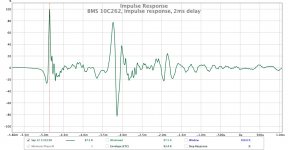
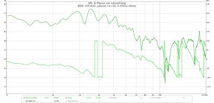
I measured time misalignment between cone and compression driver. I found out that my initial estimate was wrong. I estimated that its value was 0.17ms (6cm) but measurement showed 0.39ms (13cm). To krivium: thanks for pointing me in right direction.
I used this method Driver time alignment.
I set delay betwen drivers to 2ms and used other compression driver as timing reference. As you can see on picture, the time difference between two impulses is about 0.39ms.
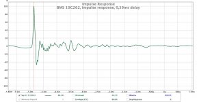
Then I aligned driver in minidsp and measured IR (the next picture) and the same house curve as before (BW36, 1/24 smoothing, 4.5ms window, 0.8m mic distance, on-axis). You can clearly see nasty dip in crossover region (1300Hz), because crossover region was badly tuned first time, due to drivers time misalignment.
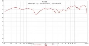
I tuned (flattened) crossover region again on both time aligned drivers, and the result can be seen on last picture. This time I used LR48 (1/24 smoothing, 4.5ms window, 0.8m mic distance, on-axis).
I did not have the time to do listening tests (and some finetuning)...but I believe it will be ok.
I used this method Driver time alignment.
I set delay betwen drivers to 2ms and used other compression driver as timing reference. As you can see on picture, the time difference between two impulses is about 0.39ms.
Then I aligned driver in minidsp and measured IR (the next picture) and the same house curve as before (BW36, 1/24 smoothing, 4.5ms window, 0.8m mic distance, on-axis). You can clearly see nasty dip in crossover region (1300Hz), because crossover region was badly tuned first time, due to drivers time misalignment.
I tuned (flattened) crossover region again on both time aligned drivers, and the result can be seen on last picture. This time I used LR48 (1/24 smoothing, 4.5ms window, 0.8m mic distance, on-axis).
I did not have the time to do listening tests (and some finetuning)...but I believe it will be ok.
Attachments
Hi Mario,
I feel that eq:ing the two peaks at 3kHz and 3.7kHz really improves the sound quality. Curious to see if you have the same experience?
Yes I do. I also corrected 500-800Hz and to some extent crossover region (1300Hz).
To make it even better, (1) start with EQ each driver to be flat not only in the passband but also at least 1 octave from/into XO region (stop band) - this means for the tweeter flat all the way down to 500 Hz (be careful with levels!) and for the woofer up to 3000 Hz. It's important that you do them one by one i.e. one should be silent while the other is measured avv. Do iterative EQ for each "way" to get them as flat as you can. (2) Now add the XO to both and then do the time alignment procedure.
(3) re EQ (global) to taste.
//
(3) re EQ (global) to taste.
//
Hi,
Thank you Mario222.
I'm glad to have been helpful.
Ok from your measurement we can deduct that at 1300hz and with your found 0.39ms offset ( 13cm) there is a 177* phase shift between both drivers.
( 343/ 1300hz= 0.2638cm ; 0.2638/360*= 0.000732906 ; 0.13÷0.000732906= ~177* )
Maybe you could try to switch polarity on the CD to see if it change rendering and measurements.
Other approach than using a 'predefined' set of filters could be envisaged too.
Food for thoughts :
Phase Shift Between Drivers - Great Plains Audio
Phase Correction for Altec Ferrite Duplexes - Great Plains Audio
Other possible option could be to use allpass filter to compensate for the phase shift...
Tmuikku and TNT advice have to be taken into account imho:
_Vituix is very powerful simulation software,
_ the approach described by TNT is the 'standard' practice in the field i evolved in. The order given is of importance and must be followed ( when you eq you change phase at the same time with IIR so it have to be performed before any attempt to time align).
I would bring a nuance to what TNT wrote however: if you use steep slope filters ( 48db and up) you can relax a bit the need for 1 octave linearisation above and below the frequency range of interest. I found half an octave to be sufficient in practice ( your milage may vary though).
Maybe it is worth investigate other xover point, maybe closer to 1,1khz?
Anyway there is room to experimentation.
Another last point, if you want to try time align your whole system, for lower way you should consider the 'wavelet method' presented by Mark100 as it gives repeatable results easily.
Hi tmuikku, I used it several times and I completely agree that it is a great tool. All my primary computers are Apple. It is the only (lame) reason I do not use it more oftenTrying to promote a bit since it truly is a great tool, and completely free to use, made for us mortals to be able to design systems that reproduce better sound. Advert writing mode off
, because it is Win based. I am aware of Win emulators though.Yes, I agree, though in this case I EQd frequency region approx. 900-2000Hz, because I am using steep XO slopes.EQ each driver to be flat not only in the passband but also at least 1 octave from/into XO region (stop band) - this means for the tweeter flat all the way down to 500 Hz (be careful with levels!) and for the woofer up to 3000 Hz.
//
Thanks, I have to digest all the inputs for a while.Hi,
Ok from your measurement we can deduct that at 1300hz and with your found 0.39ms offset ( 13cm) there is a 177* phase shift between both drivers.
( 343/ 1300hz= 0.2638cm ; 0.2638/360*= 0.000732906 ; 0.13÷0.000732906= ~177* )
Maybe you could try to switch polarity on the CD to see if it change rendering and measurements.
Anyway there is room to experimentation.
I am not sure if the first statement is correct however. The phase shift would be 180 degrees (or 177, as you pointed out,
but bear in mind please that my measurements are not "lab precise") if:
- there would be no phase shift in each driver itself, and
- I would not set the delay to 0.39ms
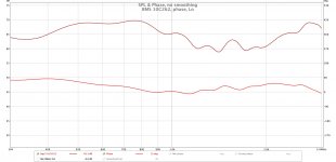
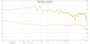
I looked at the phase of individual drivers, measured previously, from 0.8m distance. Please see attached files. You can see the phase in 1300Hz region. Cone driver is displaced by 13cm, we should subtract 180 degrees from its 12 degrees, which makes it -168 degrees at the same point, where compression driver is having +83 degrees, correct? So if we further add or subtract 180 degrees, result should be about the same. This of course might be oversimplified, because measured combined phase (when cone driver delayed 0.39ms) is about -52 degrees. See the third picture.
But definitely yes, there is room for further experimentations. This one is good too https://www.bksv.com/media/doc/17-198.pdf.
Attachments
- Home
- Live Sound
- PA Systems
- BMS 10C262 coaxial build