I just can't get my head around the 0.39ms (13cm) offset number.
The driver has a total depth of 146mm so is the acoustical center of the mid supposed to be at the outer edge of the diaphragm?
I tried with an offset of 21ms in my fir filter with a fourth order Butterworth at 1200Hz and inverting the mid today, phase looks ok in my quick and dirty measurement.
The driver has a total depth of 146mm so is the acoustical center of the mid supposed to be at the outer edge of the diaphragm?
I tried with an offset of 21ms in my fir filter with a fourth order Butterworth at 1200Hz and inverting the mid today, phase looks ok in my quick and dirty measurement.
Airvoid,
Do you have measurement gear? If yes the method which have worked for me was the one from J.Bagby or Troels Gravesen ( 3 measurements one of each driver alone then both playing without mooving anything ( no filters, just raw drivers), then you play with offset in a simulation software until you reach same profile as both playing together).
I've not had time to investigate the wavelet method but i'm sure it may be even more effective as it identify offset and phase issues easily and independently.
Worth trying it.
I wonder if Mario used some usb mic to perform measurements? If yes then they'll be flawed as there is random timing error with this kind of mics.
One of the reason i talked about the 'alternative' method.
Last edited:
Wrt delay, its not only mechanical distance that come into play, also electrical reactance do that - at least on phase level. Absolute numbers are not (so) important - just do relative measurements - thats what is important. If you can measure - ignore physical length - just do time. My 2€c.
//
//
It depends of what you want to achieve TNT.
I use FIR and for them to perform at their best you need the driver to be all on same polarity and with physical location compensated.
Of course you can just don't bother... For coax i think it make sense to have offset compensated. It was the main difference between Altec approach and Urei for example: the later being time aligned both used same 604 driver (Urei had the 'mantaray' horn treated differently with a kind of foam iirc rather than the multicell though) .
Here is some 'review' of a compensated one ( scroll down the page).
Phase Correction for Altec Ferrite Duplexes - Great Plains Audio
It match my own observations.
Last edited:
Airvoid,
Do you have measurement gear? If yes the method which have worked for me was the one from J.Bagby or Troels Gravesen ( 3 measurements one of each driver alone then both playing without mooving anything ( no filters, just raw drivers), then you play with offset in a simulation software until you reach same profile as both playing together).
I've not had time to investigate the wavelet method but i'm sure it may be even more effective as it identify offset and phase issues easily and independently.
Worth trying it.
I wonder if Mario used some usb mic to perform measurements? If yes then they'll be flawed as there is random timing error with this kind of mics.
One of the reason i talked about the 'alternative' method.
I'll share my measurement as soon as I've figured out how to post a pic. I'm running these with a 12N630 in a three way. 😀
I just can't get my head around the 0.39ms (13cm) offset number.
Exactly, it was surprise also for me too. It would be great to compare my measurements with yours or other members.
I wonder if Mario used some usb mic to perform measurements? If yes then they'll be flawed as there is random timing error with this kind of mics.
One of the reason i talked about the 'alternative' method.
I am using UMIK-1 (about 2 years old, powered from USB). The whole measurement path is this: BMS - UMIK - Mac - REW. The whole signal path is: Mac - USB hub - Scarlett 8i6 (SPDIF out) - Minidsp miniSHARC-4x8-96k - amps - BMS. I am measuring right channel, left channel is used as a time reference. There might be some latencies on signal path, but they should be probably the same for cone and compression driver.
Since we are mostly interested in phase/distance in crossover frequency, I was thinking about simple method: playing sine of crossover frequency (1300Hz) on cone and compression driver with the same amplitude (SPL), trying different delays and measuring which delay will max combined SPL. It is basically alteration of one of the method that you suggested.
And of course, changing crossover frequency in range for example of 1000-1600Hz might change results significantly, because phase of drivers in this range varies significantly.
Will try something this weekend
") .
.Can you please elaborate? I hold time and phase interchangeable/equivalent. Yes, this kind of measurement will blend distance (time) and initial driver phase at given frequency (caused by reactance) together. But the result should be the distance where cone and compression driver are in such a distance in which their relative phase is zero.
I did some new measurements. All measurements were taken from close distance, 10cm from the outer edge of cone driver, on axis, 4ms windowed, no eq/filter.
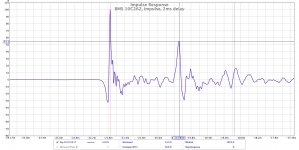
First of all I repeatedly measured delay/displacement between cone and compression drivers. I measured 0.34md from this closer distance, as you can see on the first picture.
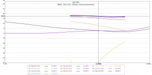
I also did experiment that I described in my previous post. It is on the second picture. I equalled SPL for both drivers in the crossover frequency (1300Hz, first two curves, bear in mind that UMIK1 precision is not better than 1dB). Then I gradually changed delay of cone driver in this sequence: curves for 0, 0.1, 0.2, 0.3, 0.35, 0.4, 0.45 and 0.5ms. As you can see max SPL is achieved approximately with delay in range 0.35-0.45ms, so it is the distance where relative phase of both drivers should be close to zero. So if you set delay of cone driver somewhere between 0.35 and 0.45ms (12-15.4cm), you should be fine. This 3.4cm interval means approx. +-20degree difference range in relative phase.
I would like to try FIR filter (crossover) instead IIR, I think it would be better option for this kind of speaker. IIR wrecks phase too much. Can you please recommend proven online (or Mac) tool for FIR design with ability to export minidsp FIR settings by any chance?
First of all I repeatedly measured delay/displacement between cone and compression drivers. I measured 0.34md from this closer distance, as you can see on the first picture.
I also did experiment that I described in my previous post. It is on the second picture. I equalled SPL for both drivers in the crossover frequency (1300Hz, first two curves, bear in mind that UMIK1 precision is not better than 1dB). Then I gradually changed delay of cone driver in this sequence: curves for 0, 0.1, 0.2, 0.3, 0.35, 0.4, 0.45 and 0.5ms. As you can see max SPL is achieved approximately with delay in range 0.35-0.45ms, so it is the distance where relative phase of both drivers should be close to zero. So if you set delay of cone driver somewhere between 0.35 and 0.45ms (12-15.4cm), you should be fine. This 3.4cm interval means approx. +-20degree difference range in relative phase.
I would like to try FIR filter (crossover) instead IIR, I think it would be better option for this kind of speaker. IIR wrecks phase too much. Can you please recommend proven online (or Mac) tool for FIR design with ability to export minidsp FIR settings by any chance?
Attachments
Here is the result on using FIR filters and equalisation. I used rePhase (really nice tool, Win based only though). I used 825 taps for cone and 825 taps for compression driver. Half of this amount would be fair enough for compression driver, and twice as much would be almost enough for cone driver, but I could not get phase right with unequal number of taps...so I kept 825 of them (I am running minidsp at 96kHz, so I am quite limited in taps number).
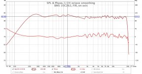
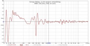
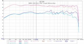
I used LR24 slope (FIR based linear phase filter) at 1200Hz and equalised amplitude/phase response based on gated nearfield FR. I was not able to get 400-700Hz region right due to low number of taps and there were some other obstacles, however this thread in non on FIR filtering, it is about BMS 10C262...so lets concentrate on it. You can see measured nearfiled FR (5cm from cone edge), gated (5ms), on axis, 1/24 oct. smoothed. As you can see phase is kept within +-20deg through all frequency range, crossover region looking good too. I measured also farfield (80cm), in room conditions, gated (5ms), on axis and off axis (30 degree), 1/24 oct. smoothed. You can se it on third picture together with nearfiled on and off (30 deg) axis FR.
I used LR24 slope (FIR based linear phase filter) at 1200Hz and equalised amplitude/phase response based on gated nearfield FR. I was not able to get 400-700Hz region right due to low number of taps and there were some other obstacles, however this thread in non on FIR filtering, it is about BMS 10C262...so lets concentrate on it. You can see measured nearfiled FR (5cm from cone edge), gated (5ms), on axis, 1/24 oct. smoothed. As you can see phase is kept within +-20deg through all frequency range, crossover region looking good too. I measured also farfield (80cm), in room conditions, gated (5ms), on axis and off axis (30 degree), 1/24 oct. smoothed. You can se it on third picture together with nearfiled on and off (30 deg) axis FR.
Attachments
Mario222, i agree with others, nice results.
Mr Klinky, there is already three project using them completed on this board (Mario222, Airvoid and another french guy i can't remember the avatar's name). All seems to be pleased with them.
I haven't heard them but have the 12c362 ( 'an older' one). I liked them and felt them to be in same league as 12" Tannoy i've heard ( but they don't go as low). Maybe the highs are more 'clean' than the Tannoy which is actually a plus for me as ime coax needs to be used in 3 way for best results ( to me at least). I would expect this new gen to be same or better.
They sound better than I had anticipated but they definitely need a bass driver imho. The cd needs a lot of finessing with the filters to get right, FIR is your friend here. I have a question in to BMS to give us a clue on physical acoustic center of drivers, I’ll share that when I hear back from them.
So, great sounding speaker, plays clear with great authority dynamics and resolution. Would opt for 12” if running solo though.
So, great sounding speaker, plays clear with great authority dynamics and resolution. Would opt for 12” if running solo though.
Great measurements thread, but what do they sound like?
I think this is a great sounding driver for very small to small venues, or even home cinema/hifi usage. As I explained previously, I needed a point source capable of high SPL, but maintaining high reproduction quality. Once you tame its irregularities with DSP, the sound is clear, detailed, with very accurate imaging.
For larger venues where you need to combine several drivers these benefits will diminish probably. Other option for point source would be for example Axi2050 by Celestion, but I somehow do not like large horns...so I used BMS.
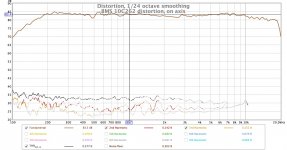
Nice looking measurements. Please show distorsion for the 5 cm trace! It would be nice to see also 45 deg...
It's mounted during meas as shown i post #1 i.e. in the grey box?
//
Here is THD measurement for 5cm mic distance. I am sorry I do not have 15, nor 45 deg measurements. I did those in previous posts (on raw drivers), I believe equalisation would not change coverage patters.
Attachments
It's mounted during meas as shown i post #1 i.e. in the grey box?
//
Yes, exactly. Measured indoor, gated.
- Home
- Live Sound
- PA Systems
- BMS 10C262 coaxial build