I'm working on this idea of a MEH cabinet but with mids and lows only. Using Hornsrep screenshots it seems hard to visualize. But I will draw this up as soon as I get some clarification.
Nd Record

ME1 Record

HR Schematic

Regarding the ME1 Record:
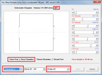
I'm assuming HR is using S2 for the location of the entry ports. Is this a correct assumption?
Ap1 and Ap2 I'm not sure about. If I'm just using a 2-inch cutout then both of these values should be the same correct?
Vrc and Lrc seem to have default values. I can't remove them. I was thinking the Nd record governed the horn dimensions as well as the rear chamber. Why is Vrc and Lrc populated in the ME1 record?
Nd Record
ME1 Record
HR Schematic
Regarding the ME1 Record:
I'm assuming HR is using S2 for the location of the entry ports. Is this a correct assumption?
Ap1 and Ap2 I'm not sure about. If I'm just using a 2-inch cutout then both of these values should be the same correct?
Vrc and Lrc seem to have default values. I can't remove them. I was thinking the Nd record governed the horn dimensions as well as the rear chamber. Why is Vrc and Lrc populated in the ME1 record?
Last edited:
I'm assuming HR is using S2 for the location of the entry ports. Is this a correct assumption?
Yes. The position of the entry point is shown in the right-hand drop-down list box. The position can be changed to S3 if required by selecting that option.
Ap1 and Ap2 I'm not sure about. If I'm just using a 2-inch cutout then both of these values should be the same correct?
Yes. If you update your version of Hornresp, you will find that the port can be flared if required.
Why is Vrc and Lrc populated in the ME1 record?
Because you have specified a vented rear chamber behind the ME1 driver. Just delete the Vrc and/or Lrc values in the ME1 Input Parameters window input boxes, or set the ME1 Vrc and/or Lrc sliders to zero in the wizard.
Attachments
Quarter Wavelength Calculations
Thanks for the Hornresp clarifications!
For the next step I'm measuring the length of the wave and this is somewhat confusing because where exactly am I measuring from or to?
I think the wavelength calculation is correct. Can someone help? See below...

Thanks for the Hornresp clarifications!
For the next step I'm measuring the length of the wave and this is somewhat confusing because where exactly am I measuring from or to?
I think the wavelength calculation is correct. Can someone help? See below...
Your wavelength calculation is correct for 67 degrees F, I use 1130 FPS, which is the speed of sound at 71.6F ...
Ideally, to eliminate off-axis response dips, the center to center distance between the cone driver exit ports should also be 1/4 wavelength (or less) distance apart. In your example, this could be accomplished simply by moving the 2" ports closer to the center of the cone.
The exit size for the driver at the horn apex (throat) appears to be approximately equal to the driver Sd, in which case the acoustic point of origin will probably be near the dust cap. If the throat were restricted enough to cause an acoustic low pass (like the side drivers) due to VTC, the acoustic point of origin would be near the baffle/port exit.
Last edited:
- Status
- This old topic is closed. If you want to reopen this topic, contact a moderator using the "Report Post" button.
- Home
- Live Sound
- PA Systems
- Multi Entry Horn - Low/Mid Box Only - Sim Help