Well, I know a lot less about amplifiers than I do about WinISD, so I don't think I can really answer that, I'm afraid, sorry.
The conversion of watts to volts for the output of the amp should be pretty straightforward, though: Volts = square root of (Watts x Impedance). Basically it's just combining Ohm's & Watt's laws. It shouldn't matter what topology the amp itsself uses, if it does 280W @ 4R, that should be the output voltage.
Cheers,
David.
in an ideal case a single rail BTL amp can generate a peak to peak voltage swing of 2* its rail voltage.
E.G 48V supply,
1) Maximum peak to peak voltage = 96Vpp
2) This coresponds to a sine wave with RMS = Vpp/(2*sqrt(2)) = 33.94 V
3) Power can then be calculated P=V^2/R = 288W (into 4ohms)
Thinking about it in terms of what is the maximum voltage swing the amplifier can put across the load will allow easy calculation of any design. E.G a non BTL amplifier would only get 1/2 the voltage swing and so would have 1/4 the output power.
Real world power is a bit lower as 100% modulation can't be achieved by the output stage and there are Rdson and other losses in the output devices and filter.
Thanks David,
And cheers kipman,
RMS not peak... Suddenly everything makes sense! Thanks for the simple step by step for the maths too
-
Turns out as well, never trust bags internal dimensions when they list them online. Turns out the actual internal measurements take off near 10L of volume.
Been doing some creating mock fitting of MDF in this bugger to see how I can squeeze it back up to 40L usable volume. (And the layout has swapped round to fit w/ ports next to the H100 horn, pictures soon)
It's 'only' 1-1.5dB of gain at Fb, but would be nice to get it back if possible..
Mylar bags filled with Sf6?
or more praticaly activated carbon:
KEF - ACE - United States
I heave heard that pearlite also works.
or more praticaly activated carbon:
KEF - ACE - United States
I heave heard that pearlite also works.
Hmm, looking into pearlite, I can't see any direct evidence or proof of it working unfortunately.
Funnily enough, in a previous role one of my projects was integrating activated carbon as a lowband absorber into commercial products. The absorption below 1kHz left traditional foams in the dust. Dust being exactly the problem we weren't able to overcome unfortunately, as acoustically transparent and almost gas tight were often at odds. (Even with some ultra-thin latex from ""special"" sources )
)
Been a bit stalled on this, as realistically the bag I had was too small. Ended up buying a new one, and now have the MDF mockup fitting nicely inside with resultant internal back to 45L. Found a local source of poplar, so just need to generate some DXFs!
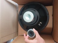
Oh, and these arrived. The 12" is hilariously light, and the 1" is simply minuscule
Edit: Didn't see your SF6 comment.. Not sure about that hah!
Funnily enough, in a previous role one of my projects was integrating activated carbon as a lowband absorber into commercial products. The absorption below 1kHz left traditional foams in the dust. Dust being exactly the problem we weren't able to overcome unfortunately, as acoustically transparent and almost gas tight were often at odds. (Even with some ultra-thin latex from ""special"" sources
)Been a bit stalled on this, as realistically the bag I had was too small. Ended up buying a new one, and now have the MDF mockup fitting nicely inside with resultant internal back to 45L. Found a local source of poplar, so just need to generate some DXFs!
Oh, and these arrived. The 12" is hilariously light, and the 1" is simply minuscule
Edit: Didn't see your SF6 comment.. Not sure about that hah!
Attachments
Some info on SF6 as a speaker filling here:
Filling a small subwoofer box with Sulfur Hexafluoride?
realistically though some other ultra dense gas would have to be used as SF6 is been phased out as its a very bad greenhouse gas. There is also someone in the thread claiming it works but I haven't tried it myself.
I also found this paper on the activated carbon, I think you would put it inside some kind of sock that allowed the gas to flow freely but prevented dust escape:
https://pdfs.semanticscholar.org/5726/ffbb8319f6c652b4e6fbbdbfc2c311fe32ca.pdf
it seems to work very well at reducing the tuning frequency of their Helmholtz resonators by upto 35%. The question for me reading this is in a ported system is the port output also going to be reduced significantly by the activated carbon?
I also found this Thesis which looks to be embargoed till August:
Acoustics of activated carbon - University of Salford Institutional Repository
*various whispering on the internet that pore size is critical
Acoustics of activated carbon - University of Salford Institutional Repository
*various whispering on the internet that pore size is critical
Nice, will probably give the activated carbon a go once I've built this up!
Bit of an update since it's been a month..
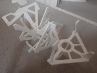
Design and FEA modelling has been finalised. All parts have been CNCd / 3D printed & sheet work cut+formed.
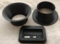
Attached a couple of images of brace subassembly, elliptical port flares and connection plate. Will try to get a screenshot of the full design CAD up at some point too.
Bit of an update since it's been a month..
Design and FEA modelling has been finalised. All parts have been CNCd / 3D printed & sheet work cut+formed.
Attached a couple of images of brace subassembly, elliptical port flares and connection plate. Will try to get a screenshot of the full design CAD up at some point too.
Attachments
Last edited:
Elliptical port flares? something like this? https://www.comsol.com/paper/download/679311/bezzola_paper.pdf
Exactly, based off a different white paper but same approach.
Velocities are in the mid 30s, so hoping to keep flow profile sensible on port exit, minimising losses at high output. Will be interesting to measure the effectiveness.
Mid section is straight pipe (less flow critical) to enable length changes.
Velocities are in the mid 30s, so hoping to keep flow profile sensible on port exit, minimising losses at high output. Will be interesting to measure the effectiveness.
Mid section is straight pipe (less flow critical) to enable length changes.
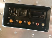
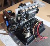
Bit more progress today, dry fit of the electronics is good (except for the poor USB panel mount connector).
Some neatening to do and a fan to add (to operate at full voltage) before it's buried under a sea of wires.
Some neatening to do and a fan to add (to operate at full voltage) before it's buried under a sea of wires.
Attachments
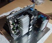
ah very neat. Your using the 3E boards and a boost converter from 12V? I found in use the 3E boards run cool.
I'm not sure how your generating the 5V for the USB charge port (presuming that's what it is?) but I had an issue with a board from aliexpress designed for ebikes for USB power that instead of generating 0V and +5V from the battery actually made +60V and +65V. This caused one of my DSP boards to blow up when I used the converter to power it (as it was connected to other circuits referenced to 0V).
This is an interesting project if you wanted to had field reconfiguration for the DSP programing (change EQ etc.): [SHARING] TCPi Interface for Sigma Studio, using ESP8266 or ESP32. - Q&A - SigmaDSP Processors and SigmaStudio Development Tool - EngineerZone
The battery pack is 43V (37v average). The I/O/II switch on the panel toggles between a direct connection to the battery or via the boost to up it to 51V.
Not entirely sure if anything unwanted will happen when switching over - fingers crossed for no fireworks.
Have stressed the boost with a 100W dummy load, and it seemed to run quite cool. Efficiency was an impressive 97%ish. The fan is more based on comments I've seen of the 3E TPA3255 running at 50V getting quite toasty.
The USB is for the USBi stick to connect to internally. They are both USB-A so makes it super easy for connections. I've toyed with the idea of having the USB-C power reversible - but keen to avoid (any more) scope creep haha.
The ESP option looks clever! Maybe I'll add it on in the future - cheers for the link!
aha I see I have the lower voltage TI chips that get less hot (TPA3251?) due to lack of TPA3255 availability when I built mine.
With my 3E amp boards they have a surface mount white LED that flashes to show clipping, if you wanted some more feature creep you could route that signal to an external indicator.
With my 3E amp boards they have a surface mount white LED that flashes to show clipping, if you wanted some more feature creep you could route that signal to an external indicator.
Ok, the build is progressing.. And it makes noise! I have tuned the port by impedance, good news is that I could accommodate the change in the design and it's a nice 30mm shorter ")
But I have hit two snags that I don't seem to be able to overcome:
1. The LED when connected to CLIP_OTW and GND, with a 47R current limit resistor always seems to be powered on slightly? And when it is supposed to clip / light up, instead it dims slightly? Changing resistor value doesn't seem to change behaviour weirdly.
2. I am getting a bit of a racket from the module when its bluetooth is active. Here is a video. It's worth mentioning that the noise floor is great when the BT isn't working. Also disconnecting the various DCDC converters and running off battery doesn't seem to help.
Not sure what else I can do for the bluetooth. Disconnecting the BT module and using the RCAs solves the problem.. But that's not an ideal solution !
Ok, so an update on the electronics:
1. Turns out the CLIP_OTW is a pulled high for OK logic output, so obviously unsuitable for driving LEDs!
I have replaced the on board SMD LED with one on flying leads and replaced the tiny SMD current resistor, but it only has source of 1.6V from FET and barely turns on the 1.8V Vf of the LED.
If anyone has any bright (gettit?) ideas of how to easiest get this LED to function that would be fantastic. I guess either to feed it higher voltage (perhaps the 3,3V generated on board through a separate transistor), modify the existing FET or circuitry, or to find a lower Vf LED (impossible it seems).
2. Major bluetooth noise is avoided by using the USB input instead. Seems that there's something in the on board 5-12v regulation circuit that is responsible for it.
Could be with the BT that the onboard regulator is overloaded?
This article turned me off using BT for audio:
Audio over Bluetooth: most detailed information about profiles, codecs, and devices / Habr
I always thought it sounded not great and this has justified my view.
On my 3E amp board the onboard LED is white which should have a higher Vf than other LED colours, have you tried a red external LED (this should have low Vf)?
Potentially, haven't looked at the components round there to be honest. Weird that it happens, but glad it's fixable.
Interesting article, I'll AB it vs the RCA in. I'll be honest, I struggle to hear the difference between line and good BT implementations! Maybe I have ears of mud
I think they must have uprevised, mine are (were) red
Interesting article, I'll AB it vs the RCA in. I'll be honest, I struggle to hear the difference between line and good BT implementations! Maybe I have ears of mud
I think they must have uprevised, mine are (were) red
Whoa, I didn't know other people were into making portable gear! My kind of crowd, lol.
@zerokelvin99 really fantastic looking work, especially the bracing. What FEA package and what's your setup strategy; are you looking at pressure vs. displacement?
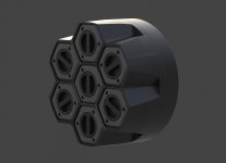
Portable battery pack design is my core project, and then I build utilities around that; motors, lighting, audio, ac, etc. At the moment the focus is on a 7s7p 2170 735w pack that does not require tab welding. You just drop in the cells, in other words.
Breaking gear into categories, like what one person can reasonably carry on a trek, is the way to go IMO. To my mind, there's grab-and-go type portability, next up will be "trekkable" equipment like your pack, and then I think rack mount is the next progression. With batteries I'm working on a rack style dock and then the individual packs would be of the grab-and-go size. Once a utility is attached to one it would likely then fit into the trekkable category.
Here's the current 7s pack iteration-
@zerokelvin99 really fantastic looking work, especially the bracing. What FEA package and what's your setup strategy; are you looking at pressure vs. displacement?
Portable battery pack design is my core project, and then I build utilities around that; motors, lighting, audio, ac, etc. At the moment the focus is on a 7s7p 2170 735w pack that does not require tab welding. You just drop in the cells, in other words.
Breaking gear into categories, like what one person can reasonably carry on a trek, is the way to go IMO. To my mind, there's grab-and-go type portability, next up will be "trekkable" equipment like your pack, and then I think rack mount is the next progression. With batteries I'm working on a rack style dock and then the individual packs would be of the grab-and-go size. Once a utility is attached to one it would likely then fit into the trekkable category.
Here's the current 7s pack iteration-
Attachments
- Home
- Live Sound
- PA Systems
- Backpack challenge