FLH's make a lot of sense, maybe it would be possible to make modular boxes with only two parts each.
I think it's a very big advantage to plan ahead for a bit, doesn't matter if you're not going to build them within a year. Better to just go at it and start fiddling about with designs and amp solutions, most likely you'd go through several iterations before you end up with something you are more happy with.
Edit:
Was just thinking, perhaps it would be easier to not make modular boxes, but instead have some kind of aluminium ramp to lay on the back. Get some big-ish wheels like for wheelbarrows on one end of the horns, and make some kind of system on one of those two wheeled trolleys, so you can just pull the whole thing. Should be possible to make it relatively compact and electric powered in case you want to reduce need for help when loading/unloading.
Last edited:
I have been doing some work on the sub amps as this is free to do in simulation land and could bring in some money for the rest of the system. Scaled them back to 300Vdc bus full bridge which should give a 5kW/8ohm burst rating. The actual amp will be a low frequency ~50kHz switching IGBT full bridge. Main complexity is the power supply (3kW maximum throughput, smooth transition between current source and voltage source behavior) but I have made good progress on that.
Mainly for cost reasons we will have to go FLH on the subs as otherwise we won't have the output per driver we need. I like the idea of just backing the subs into the van. I try to make my system fast to setup/teardown using patch panels and multicore cables for less stress.
Mainly for cost reasons we will have to go FLH on the subs as otherwise we won't have the output per driver we need. I like the idea of just backing the subs into the van. I try to make my system fast to setup/teardown using patch panels and multicore cables for less stress.
15 inch Beyma in 20 litres sealed
I have never designed a front loaded horn so please bear with me...!
I have a pair of the Beyma 15 P80 running in 21 litres sealed box and crossed over at 500Hz to a broadband driver.
I use DSP to crossover and Eq the sound and the results are awesome!
I bought the speakers second hand on Ebay and dont have any spec or info except air volume and driver model, they are about 3 years old I think.
The attached sim is interesting and suggests that about 21 litres is the min sealed volume to stay below the 0.707 Q.
Maybe adding a front-loaded horn changes the rules but I would be cautious about 10 litres... Maybe actually build a test cabinet of 21 litres and then add polystyrene cubes to "reduce" the internal air volume and you can measure/listen to actual results Vs Sim? Its a great way to be sure and its soooo much easier to remove polystyrene blocks than build a bigger box!
Good luck and great project!
A.
Attachments
Hi Alex yeah the rules are a bit different in the FLH. The rear chamber is sized to 'reactance annul' (cancel the imaginary portion of the acoustic impedance at the throat), this increases efficiency near the horns low frequency cut off. More simply the rear chamber has to be smaller because the air load on the front of the driver is larger so a stiffer 'spring' is required.
Thanks for the explanation, it sounds logical.
Some simple but effective looking horns here:
https://www.ddshorns.com/BassMid DVB 15N pro.pdf
and here: https://www.ddshorns.com/BassMid DVB 15H.pdf
The shallow one reminds me of the ones I used to use when we needed extra throw in venues where the stacked sealed subs needed a boost.
The cabinets had optional spacers which allowed us to stack as sealed subs or stack with the front horns on.... It always sounded good either way!
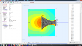
I learnt to use Akabak 3 so simulated the horn in that. Response drops off a bit earlier than Hornresp as effects like cancellation across the diaphragm are simulated. I don't want a phase plug so will probably cross to the M200@450Hz or 400Hz to avoid the issues that are happening >500Hz
I have attached the simulation, there is considerable scope for optimization like only simulating a quarter of the horn. Simulation is freespace.
-6dB beam widths:
Beam width H@400Hz =76 degree
Beam width V@400Hz= 108 degree
Beam width H@450Hz= 66 degree
Beam width V@450H= 98 degree
I have attached the simulation, there is considerable scope for optimization like only simulating a quarter of the horn. Simulation is freespace.
-6dB beam widths:
Beam width H@400Hz =76 degree
Beam width V@400Hz= 108 degree
Beam width H@450Hz= 66 degree
Beam width V@450H= 98 degree
Attachments
Your 149db requirement from mono cluster but 143db for split stacks on sub confuses me a bit because 2 143db split stacks dont do 149db summed as physically split sub stacks will have issues summing constructivly throughout the passband.
without colocating your sub and midbass cabinets, a 100hz crossover may prove difficult to successfully implement without signidicant changes to response as you walk around the listening area.
without colocating your sub and midbass cabinets, a 100hz crossover may prove difficult to successfully implement without signidicant changes to response as you walk around the listening area.
I had envisaged a continuous line of sub bass cabs at the front of the stage from left stack to right stack.
At the moment we actually have access to a very large amount of reflex subs so that's what we would be using... when your allowed to have gigs... until enough money builds up to build horn subs.
At the moment we actually have access to a very large amount of reflex subs so that's what we would be using... when your allowed to have gigs... until enough money builds up to build horn subs.
First gig
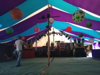
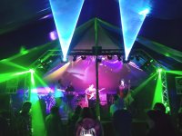
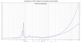
The horns have been completed in the past few weeks and had their first gig at the Palais de Phonix stage at Sol Fest. Very pleased with how they turned out, plenty of headroom. This was especially noticeable as I was operating them in the same range as the lower horn on the orbits but ended up trimming the orbits down 6dB and the midbass horn up 6dB as the orbits amps where starting to clip on some acts. I do have some measurements and they look close to simulation in response but I have an absolute SPL calibration error so will retake the measurements when I have a calibrator to work out what the issue is. Lots of positive comments on the sound and the horns are an easy two man lift.
The horns have been completed in the past few weeks and had their first gig at the Palais de Phonix stage at Sol Fest. Very pleased with how they turned out, plenty of headroom. This was especially noticeable as I was operating them in the same range as the lower horn on the orbits but ended up trimming the orbits down 6dB and the midbass horn up 6dB as the orbits amps where starting to clip on some acts. I do have some measurements and they look close to simulation in response but I have an absolute SPL calibration error so will retake the measurements when I have a calibrator to work out what the issue is. Lots of positive comments on the sound and the horns are an easy two man lift.
Attachments

Big fan of the orbits for the price. I would get the midbass driver upgrade if ordering them as it boosts efficiency and power handling in the lower midrange (we have both with and without upgrade types and ran separate processing for them). If you don't have a massive midbass horn to take over you will want this for bands. For electronic music genres we have always had lots of headroom with them (as its mostly sub) but during Kaya project (our biggest act)* we also started to get some gain reduction on the average power limiter for the tweeter so it might also be worth getting the tweeter upgrade (our orbits have the standard Fane tweeter). Our limiters may be quite conservative though as nothing seems to be getting hot.
I have the DSP settings from Soundgear but they didn't make sense to me with lots of very high Q PEQs so I run my own EQ based off measurements of them. The fidelity of an orbit array is not as good as my own PA tops but much better than typical PA speakers (once properly processed).
*we where about 105dBc - 120dBc, 90 - 100 dBa (slow) at the mix position during Kaya project which is the position the last picture was taken at.
Last edited:
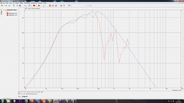
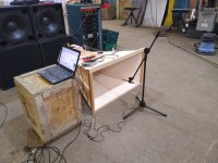
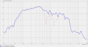
Here is the measurement data I have. I used a UMIK-1 (which I subsequently checked for frequency response against another microphone) correcting for distance and level adjustments the sensitivity is too high to be plausible. I have therefor just adjusted the mid-band sensitivity of the measurement to match simulation. Measurements where also not exactly ground plane taking place in a large industrial building at 3m and have been smoothed 1/6th octave. Hope to drag it outside and get a SPL calibrator so I can find the actual sensitivity. I know its more sensitive than the 3 orbit array in the above picture.
Impedance sweep shows that the rear chamber might be oversized (shifting of lowest resonance peak) this doesn't seem too critical an issue.
Impedance sweep shows that the rear chamber might be oversized (shifting of lowest resonance peak) this doesn't seem too critical an issue.
Attachments
Last edited:
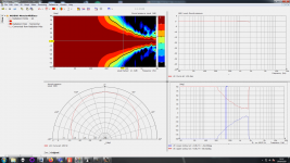
I improved the simulations of this horn after learning more about AKABAK3. The new simulation of the horn (attached) in free space uses a quartered model, simulates in only a few seconds and had no weird behaviour beyond 500Hz. Key was to make the interface between the internal and external calculation domain to be a one side open box rather than a plane.
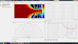
I also learnt how to process the beamwidth data better... weirdly it looks like I would be better off running the horn on its side if I want to cross over at 500Hz! for a nominal 90x60 pattern (oops). Although I think also a 400Hz crossover in the conventional oriantation would be acceptable.
Also it occurs to me that the horn was measured on the floor (half space) and my simulations are full space so I should simulate the horn in half space as well. When the weather warms I should be able to measure the horn outdoors and get some real world polar data, but I don't expect great deviation from simulation.


Horizontal normalised polar:

Vertical normalised polar:

I also learnt how to process the beamwidth data better... weirdly it looks like I would be better off running the horn on its side if I want to cross over at 500Hz! for a nominal 90x60 pattern (oops). Although I think also a 400Hz crossover in the conventional oriantation would be acceptable.
Also it occurs to me that the horn was measured on the floor (half space) and my simulations are full space so I should simulate the horn in half space as well. When the weather warms I should be able to measure the horn outdoors and get some real world polar data, but I don't expect great deviation from simulation.
Horizontal normalised polar:
Vertical normalised polar:
Attachments
- Home
- Live Sound
- PA Systems
- Mega midbass straight horn 139dB