So I now have a DBT.
I tried reflowing the the broken solder joint last time but didn't test it again until I got the tester. I've turned it on now. The bulb lights up bright, goes dim then a bright flash when the relay clicks then remains dim. It don't always flash bright when the relay clicks every time I turn it on.
I tried it through a scrap speaker, sounds clear and well, much better than before, upto just past quarter to on the pot, then distorts again.
I'm planning on ordering some copper foil, redoing the joint completely.
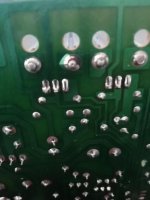
The broken joint is on the regulator heatsink, there's two legs on each heatsink going to the board.
Is it a good idea to link a insulated solid core wire to both legs for a better connection?
Can the regulator still be faulty as I understand they distort if they are faulty? I'll order if its a possibility
I tried reflowing the the broken solder joint last time but didn't test it again until I got the tester. I've turned it on now. The bulb lights up bright, goes dim then a bright flash when the relay clicks then remains dim. It don't always flash bright when the relay clicks every time I turn it on.
I tried it through a scrap speaker, sounds clear and well, much better than before, upto just past quarter to on the pot, then distorts again.
I'm planning on ordering some copper foil, redoing the joint completely.
The broken joint is on the regulator heatsink, there's two legs on each heatsink going to the board.
Is it a good idea to link a insulated solid core wire to both legs for a better connection?
Can the regulator still be faulty as I understand they distort if they are faulty? I'll order if its a possibility
Attachments
I sometimes fix burnt out PCB traces with a length of wire. Signal wire I use solid core 28 ga kevlar (which doesn't burn with my soldering iron). Driver current can to up to 5 amps so I would use 20 or 18 ga for that. I drill a hole through the circuit board next to where I am going to attach to, using a small drill and a pin vise. If the PCB is well supported with nothing fragile behind it I'll use a hand crank Yankee drill. The drill pops through the board and goes down to the chuck usually, so you have to plan for that and that is one reason I don't use an electric drill. Too much possible damage.
Then I push the wire through the hole from the component side, and bend over on top of the trace I am trying to splice. Then I solder the wire to the existing trace.
Same with the other end.
Supported by the board like this, the patch wire doesn't tend to fall off.
I wouldn't randomly replace parts to fix a distortion problem. It could be a bad solder joint, or in the case of a Peavey MMR-875t I'm listening to, the front board has to be tightly screwed to the front panel for the signal to not be distorted. (???) (Hard to diagnose with the front panel off for examination.) Any resistor or cap could have a bad weld inside the case, or even transistors & diodes for that matter.
You need to use a scope or sound probe to determine exactly where the distortion is coming from. A sound probe is an amplifier & speaker, protected against DC voltages and against excessive AC voltages. Useful test amplifiers are old PCAT speakers or somesuch low power speaker/amp. Ahead of a 2 vac (line level) or so amplifier input, I'll put 47k resistors on both signal and return. Ahead of that I'll put .047 uf capacitor 400 v rated or higher. Then across the end of capacitor & signal ground, I put line to line 2.1 v zeners, or red LED's. This clamps the input voltage to 2 vac. Then ahead of the zeners I put a 1 k resistor on signal and return. This limits the current on the zener or LED.
Then I can connect the current protected amp return to speaker ground or RCA ring out, and listen through the sound probe/amp to the music at the test point.
If the unit has a flying speaker ground as Peaveys often do, you have to put a .047 uf cap also in the line from sound probe amp ground to unit under test speaker ground. Ahead of the 2 zener voltage clamps and after the 1k resistor.
I use a couple of insulated alligator clip leads or pamona grabbers to connect the sound probe to UUT(unit under test). Much cheaper than a scope probe which is a minumum $60 to replace if you step on it. Audio isn't supposed to go over 20 khz, and even parasitic oscillation is often a mhz or two, which can pass through insulated wire a couple of feet without much attenuation.
When connecting the probe, expect a big pop as DC voltages are equalized by the caps. But after that you should hear what is going on in your unit under test. Turn listening amp gain down in the beginning then turn up as you decide you're not hearing the music coming in your system. (I use a battery FM radio as signal source, turned down to 2 vac out the earphone jack. You don't need the 7 vac a radio will put out at max volume. )
Then when you find the exact point where the distortion starts, you try pressure with a stick or circuit cool spray or a heat gun to determine exactly which part is causing the distortion.
Happy hunting.
Last edited:
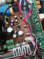
Thank you so much for your detailed reply and information as I find it fascinating and really enjoy the sharing of your experiences and knowledge. I can imagine your Peavey front panel distortion dilemma was a nightmare. Are they earth screws that need a tight solid connection? I noticed the two screws on this Peavey PSU board were rusted, cleaned them up as best I could. I also noticed, after I put it back together one of the purple caps connection didn't seem good. With gentle wringing one of the joints seemed to 'click' that I could hear and feel when moving it, I'll reflow that next time I remove the board.
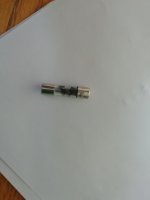
Update on the Bose, the front panel fuse is well blown, I can't remember actually checking it previously yet I'm sure it was checked as it's always the first thing I do. This led me to thinking there may be a problem with the output transistors. Like the last time I checked them in curcuit with a MM I checked for continuaty between collector and emitter I get a numeric reading of the same number on both channels but no beep, not sure if it's the cheap MM I'm using being insensitive though?
On the Peavey I'll order some copper foil later but not sure what to use to cover the foil, I'm guessing some kind of fibreglass, never repaired one fully before, only bodged one by scraping away and soldering across the track on a cracked board. I will link a wire across the legs to ensure solid connection, I was thinking solid core mains cable you use in walls if its OK?
So much appreciated the help, I always re-read replies I get on here as your guidance is superb!
Attachments
Mains cable is typically 14 or 12 ga. suitable for 15 to 20 amp currents. No single transistor can pass more than about 5 amps. Too thick a wire when soldering could cause the traces on the board to melt further. So 18 to 20 ga patch wire over a burned power transistor land is fine. I reallize you buy wire in metric sizes, I'll attempt the conversion: wikipedia says 18 ga is 1.02 mm and 20 ga is .812 mm, so any wire you can buy at the auto supply or home store between those sizes is fine.
28 ga for signal transistor areas is .32 mm. .5 mm or .64 mm wire probably won't burn up the silicon junctions.
The actual reading of the transistor you got with the dvm is important. Beep is for continuity, if resistance is that low the transistor is probably shorted. .450 to .770 v are normal readings for silicon transistor junctions. schottky diodes .250 to .450 .
Should go much higher backwards, but not usually to infinity ---- as other circuit parts will take off current.
Last edited:
Great advice again. I'll get some 18 or 20 gauge wire as you advise and makes sense.
I so prefer the American way of categorising wire thickness. So much easier and simple.
The transistors were 509 on one channel and 514 on the other. Can't remember if they were 0.509 etc as I was more interested in them not beeping. I'll check again when the MDL 10A fuses get delivered. With a lot of luck that's all it needs but doubt it very much.
I notice your Peavey is the CS series. Not heard a better amp for driving subs yet than those beasts.
I don't think my DVM puts a point in front of the reading on "diode" scale either. Those readings are fine forwards.
I love the CS800s, but I bought it damaged and very old.I bought a whole band setup for $1000 including 2 SP2-XT speakers that work great, and a 12 input mixer that's fine. On the CS800s I've fixed the burnt out input resistors (probably 75 W guitar amp plugged in the input jack). I've fixed the burnt out fuse in the switcher supply and the overaged electrolytic cap that shorted out. But it still has a channel volume imbalance, that someday I'll address by changing every e-cap, plus whatever else? Was very good sounding, just uneven. Meantime I need about 70 w/ch in my music room, and 400 w/ch is overkill. Meanwhile bought a Peavey PV-4c "for parts or repair" for $28 including freight. $20 in output transistors & $28 in rail caps put it back in service, runs 2-3 hours a day in my TV room, replacing the Samsung "sound bar" that I didn't buy. Those 32" flat screen TV's sound awful.
Got salvage Toshiba 6" projection TV drivers in Newark boxes with a reflex port in the back on the PV-4c, sounds very decent on the PBS concerts.
Wow, that is overkill for your house, surprised the house hasn't moved down the block haha. You appear to quite enjoy buying broken gear and fixing it up and seems great when your as knowledgeable as yourself.
I have a few QSC and a couple of Crown out on hire, been running for years with no issues. I do go to their location and remove the dust on them all every six months though, take out the fans and clean them with distilled water. I have a soft spot for QSC and older Crown, Yamaha dual monos and Peavey Cs amps.
I got a bargain a couple of weeks ago. I had a Pioneer A-333 hifi amp for sale that I bought filthy for £30, cleaned it inside and changed a few worn caps and resistors and was offered £40 and a Crown XLS 402 too. I don't like it too much but couldn't turn the offer down.
The guy was a retired DJ, said he barely used it over the two years since he bought it. There wasn't too much dust in it so believable. Works fine, just missing volume knobs and power button, I had some knobs about spare so just need to find a button.
I was going to post if there's any improvement I can make to it. Thinking better heatsink on output transistors and possibility of adding a heatsink to bridge rectifier. Increasing the x4 3,300uF caps to x2 6,800uF or x 4 4700uF?
I'll be using it at home running some 250w rms speakers with 2 10" midwoofers per channel. The amp is allegedly 300w per channel at 8 ohms, I doubt that, I don't need more power but do like to keep it as cool as possible.
Interesting to hear your opinion please
Attachments
The PV-4C had 3 previous sets of output transistors installed before I put the 4th set in. 3 sets of initials on the heat sink? So I had some idea that heat sinking was not adequate?
I added as many of these flattish heat sinks as I could fit in, https://www.newark.com/aavid-thermalloy/7019b-mtg/heat-sink/dp/18M8222
Only I used TO-3 ones I had around. aavid-thermolloy 506007b00000g which I paid $.88 each for years ago. Lots of fins.
Digikey has something similar now: 506007B00000G Aavid, Thermal Division of Boyd Corporation | Fans, Thermal Management | DigiKey
I drilled & tapped the heat sinks for #4 US machine screw, added compound and screwed them down.
I then tied bulk filter material over the fan grill, to prevent buildup of dust balls.
I also changed the shutoff snap action thermostat from 100 C to 70 C. I had that laying around too.
That one still runs the fan on high sometimes @ 2 W/ch in my TV room. I might install solder terminal strips to read the emitter current idle bias someday. I used MJ21193/4 and the OEM was MJ15024/25. If that changed the idle current I'll be sorry. Don't leave them on very long, 4 hours max some nights.
Might have just been a case of performers tripping over the speaker cables and pulling the 1/4 phone plugs out over & over, but you'd think a band would move on to dual banana plugs for speakers after the first or second time blowing the output transistors. Maybe they don't read forums.
The bridge rectifier had no initials by it so I didn't worry about it.
Peavey seems to get rated power out of 3300 uf rail caps so I didn't upgrade. If your going to double caps, it seems to me you need to put a cl101 or some NTCR in series with the primary of the transformer to keep the room lights on at turn-on.
Last edited:
Sorry for the late reply, been busy with my daughter and teenage drama... The joys haha
Very interesting mods you did there, impressive. It sounds like you improved the temperatures. I see what you mean with bands not being bothered about their gear, as long as it plays that's all they bother about, not everyone but a lot. Bare speaker wire touching chassis is so common, my brother does it with the Peavey but there's no telling him and hates advice. It has speakon connections FGS, he didn't know the plastic stoppers come out for banana plugs connections but I doubt he will do that. I'll just put 3300uF quality caps in my Crown to replace my hated unreliable Jamicon.
I've made some progress on both amps, seems similar issues.
Bose amp:
Fuses were delivered, now powers on into protection mode. When sequence button is switched on (down) when powered up the dim bulb is very bright, the fan kicks in yet no relays click, they buzz quite loud as well as the transformer. Still unsure how to check output transistors with the DMM as I get no beeps. When sequence switch is up on turn on then pushed down no fan kicks in and dim bulb isn't as bright.
Peavey amp:
I only checked one channel through the speaker. The distorted one. Turns out the other channel is dead. After I tapped the output relay on that channel it started buzzing. I took the channel out and a wire with a spade terminal pulled straight out of the board with its pins left in the spade. So that needs resoldering back in. One of the transistors screws were totally rounded off, like one on the front panel and two on the psu board, does my head if someone didn't use the correct sized screwdriver or just used a drill. Anyway I was wondering if the bad spade connection on the dead channel is something to do with the buzzing relay or is the relay faulty?
Last edited:
speaker relay connections often get high resistance in their old age. Peavey relays are better than average, but worth a check. Check the voltage across with the amp putting power in a 8 ohm resistor or something, ie the volume up. These big amps should drive a 6 ohm tea boiler okay. Use an ANALOG meter, DVM average over 2-4 seconds and smooth out the bumps to nothing. $29 5000ohm/volt meter from hardware store okay for those tests as long as has a 10 v scale.
On the bose check the DC voltage at the input to the protection relay. If over about 200 mv there is a problem in the amp circuit. Must trace DC back to origin. I found in the PV-1.3k the input op amp had a bad solder joint to the minus pin, worked sometimes, sometimes put output at 180 vdc. I think 4 techs had been in there since 1993 and not found that. Had a label on the speaker terminal "DO NOT USE CHANNEL A". Poking bad solder joints with a plastic stick helps. Also a meter probe.
On the bose check the DC voltage at the input to the protection relay. If over about 200 mv there is a problem in the amp circuit. Must trace DC back to origin. I found in the PV-1.3k the input op amp had a bad solder joint to the minus pin, worked sometimes, sometimes put output at 180 vdc. I think 4 techs had been in there since 1993 and not found that. Had a label on the speaker terminal "DO NOT USE CHANNEL A". Poking bad solder joints with a plastic stick helps. Also a meter probe.
Last edited:
Again, fantastic guidance. I'm sure I can handle doing that in the morning. Your a superb help, can't thank you enough. I'll also look for an anolog meter too. I heard previously they are more precise so I think it will be a great tool for the future. I'll get a scope and a signal generator when I get Christmas out the way.
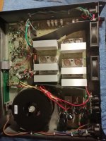
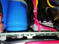
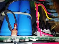
I found a problem on the Bose while going over the service manual and going through the amp before taking it apart. One of the big filter caps has a burnt screw and burn marks on the board around the screw. Only one of the four 22,000uF caps has the issue on its negative terminal. I guess it's a clue to what's gone wrong and probably a screwed capacitor. Is it likely something before the caps has gone causing the damage?
Electrolytic caps are the time fuses of electronics. The production engineers & marketing pick a time they want the amp to blow up. Some brands 1 year, some brands 20 years. Then they buy that quality electrolytic capacitors. Epoxy sealed capacitors were made in the 70's that would contain the water "forever". Nobody but Fender & some medical suppliers used them. Ask a guitar amp repairman about green CDE capacitors from the 70's.
The big question, is the transformer or rectifier damaged? Before buying $80 in caps (and screw terminal caps aren't cheap) you need to load the transformer with a 8 ohm 600 w tea boiler or log resistor. Then plug in, make some heat, read the value of the AC coming in from the light bulb box. 80% or lower of wall voltage, your transformer may have a shorted turn. Use an alligator clip to read voltage over 25, from one hand to the other it can stop your heart. No jewelry on hands or neck.
Rectifiers can be measured with the transformer unsoldered. .55 to .75 v forwards, ---- or 9999 backwards on diode scale.
BTW when shopping for scope, make sure it will cover these high voltage amps you work on. Many inexpensive ones only go to +- 60 vdc. Then there are the x10 and x100 probes, which are not cheap if you step one.
Just replaced ALL the e-caps in a farnell brand "Stellar Labs" HDTV converter DT400. 8 years and started hanging up & rebooting. Back to new performance. Getting ready to put all new e-caps in a Compaq 14" CRT display that lasted 15 years. Still works for 10 minutes before the horizontal circuit messes up. Using that to replace the Samsung 32" LED tv that lasted 23 months before quitting. Model UN323400DBF if anybody is thinking buying one of those pieces of instant garbage.
BTW when putting in new e-caps, try to buy the longest service life available. 3000 hours @ 85 C typically for 3300 uf up, smaller ones 10000 hours @ 105 C. Farnell & digikey will show you in the selector table if you ask, Mouser makes you download each datasheet & read it. Don't know what RS does. I have no contact with the German distributors. Brands to respect Nichicon, Rubicon, Panasonic, Vishay. 2nd tier CDE, United Chemicon, multicomp (farnell house brand). Some houses won't tell you what brand & part # cap they are selling. Stay away; I got average 8 years out of TV parts store e-caps before the debit card was invented.
Last edited:
I'm learning so much from you and confirms some of knowledge I've learnt in the last 12 months too, especially about the capacitor brands and history. I like the Panasonic (FR mainly) and Nichicon (PS/PW) for power supplies and standard Nichicon/Nippon for signal paths. I feel the Japanese caps are my favourite yet won't mind using Vishay or Epcos neither. I will struggle getting the same sized Nippons like these. I've found some same brand wider and less taller ones in Ireland with one value higher voltage, which I'd prefer, yet that means I'd have to move and remount them running a wire with them ring connectors I'd think. If I have to move them it opens other brands options up and RS Components (which one is walking distance from my home) have good options and prices on this size.
Before I buy anything I'll get the PSU out, check the rectifiers properly then check the transformer like you kindly explained well. We call a tea boiler a kettle over here and never seen one below 2,000watts, our mains voltage is higher I guess. I'm surprised you use an electric tea boiler, I thought Americans just use stove ones that whistle. I like both.
I also noticed another 22k cap negative terminal has white marks like heat marks.
Great advice on the scope, no doubt I'll come back to this thread before I buy it to make sure, like other things.
I like how you improved the reliability and fixed your TVs. I did the PSUs in my LG and Panasonic TV recently with good caps. Also fixed the PSUs in my washing machine and electric shower, replaced Capxon caps with Panasonic, unbelievable improvements, my washer is louder than before it broke now to say the least lol
I'll take a look at both amps later today, I recapped a 90s Pioneer amp last night, the DBT takes away nerves as well ha
Hi again,
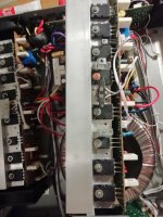
I managed to get back onto fixing the Peavey amp up. As I had the dead channel out loose I thought its best to use some new mica pads and grease (Servisol heatsink compound). It had previously had thick layers of paste on them, I managed to get a thin layer on except two transistors as one had the rounded screw so needed desoldering (which the trace on one leg was broke) and the C5198 had a smaller pad so left that. Is it supposed to be isolated? It has a metal back.
The last screw on the transistors snapped, I've never done this before so that's all I needed. I mana to get the snapped screw out without disassembling it all again. I put a steel copper plated replacement in, will it be OK?
I ended up selling the Bose for S or R for £130 on ebay. Was sick of seeing it and Bose ain't my favourite brand. Bought a working Peavy GPS 3400 working for £100,well happy with it for that price.
If this channel is OK I'll put it back together and finish the repair on the PS board regulator.
It's been challenging lol but enjoying 😁
Never seen a copper plated steel screw before. Shouldn't be any electrolisis of that with copper board leads. I'm using stainless steel screws with plain steel washers for replacements. I might regret that some day.
On my PV-1.3k the TO220 predrivers weren't isolated from the heat sink. The heat sink was out in the middle of a green circuit board so isolation wasn't important.
I like Peavey's full disclosure schematics. Crawling through a Peavey Q205 graphic equalizer today. Some dingbat repairman had signed across a number of traces with a marker, and the channel was crackling before I erased it with alcohol. Now the other channel is low output, wish I had the layout tonight. Needed one output by Sunday, put a PV8 mixer into the organ amp to mix in a wired lavelier microphone with organ tone generator, and it whistles that way. Will use the Q205 equalizer to kill the frequency of the whistle. Regular church PA started crackling last week, 15 years old, instant junk. It's a Sennhauser radio mike base station crackling, I'm afraid to work on those, probably all surface mount it is so tiny. Allen organ amp had 100% new electrolytic caps in 2017, should be good for 37 more years. Allen amp was age 37 when it failed in a service due to bad caps.
Last edited:
I have some copper plated screws from dead Pioneer and Marantz hifi amps. These were the transistors screws. I used the same copper washers, wasn't sure if using the previous washers the Peavey had would have a corroding effect from the mix of different metals. The hifi amps had a aluminium heatsink so presuming they were OK. I only know they are copper plated as I had one pioneer amp which the bottom panel was rusted from something spilt and left to rot. The copper plating came off the screws and some were steel, possibly stainless, not sure tbh.
Very interesting in your current work. I not a fan on the surface mount components. I can see them good, just the heat from components and surface mount components being so close together. As I've seen you give good advice to others on this site, heat is the enemy. I like things to run as cool as possible.
I still had no luck finding schematics for this PVi, would like to adjust the bias, think it has DC offset adjustment too if I recall. Mind you if I had the schematics I'd recap it with good Japanese caps. These cheapo caps claim to be 105°, I thought the difference between 85° and 105° was just the aluminium structure, not sure though, these seem to have thin aluminum.
I love graphic equalisers in PA, although mobile DJs around here seem to have them smiling everywhere they go with no adjustment on them or even bass and treble on the mixers. I can't stand them in hifi. They were a trend in the 80s and 80s Hifi lovers don't know no other way and used to their sound.
So does marking the traces cause distortion?
- Status
- This old topic is closed. If you want to reopen this topic, contact a moderator using the "Report Post" button.
- Home
- Live Sound
- PA Systems
- Bose 1800 series VI Pro amplifier not turning on & Peavey PVi 3000 no output