There are two options. There are PFETs that will work, including TH FETs but the choice becomes limited. The integration of the SMD pad is virtually no work. The FET gate position is in the same place as the base. The FET can be mounted on the underside of the board if necessary. If the FET is symmetrical then it can be mounted topside.
Let's call your version the P version and my one the N version. Doesn't the PCB work for both if you swap the power rails and reverse the decoupling caps? That was the advantage of removing the opamps. I would hope you got more than one proto PCB made.
Let's call your version the P version and my one the N version. Doesn't the PCB work for both if you swap the power rails and reverse the decoupling caps? That was the advantage of removing the opamps. I would hope you got more than one proto PCB made.
Yes, I ordered five of the first PCB version. I used JLCPCB, and the boards seem to be very high quality. By this point I've changed out a lot of parts in the one I've populated, and so far the pads have held up extremely well.
I'm presently working on adding the SMD pads. One question, however, is what the 22R resistors (R14 and R15) are doing in your spice simulation.
I think that if I'm clever about this I can make one PCB work for both.
I'm presently working on adding the SMD pads. One question, however, is what the 22R resistors (R14 and R15) are doing in your spice simulation.
I think that if I'm clever about this I can make one PCB work for both.
Yes, precisely. The additional resistors might help with the jump in gain issue. I don't know. Try it. I hope you are sitting comfortably.
The basic concept is an amp gain block. Anything that an opamp can do, this can do. So visualize an 12 pin module. The transistors are connected. 10 connections are for the collectors and emitters. 2 connections for input. Since the pin-outs of SMD P and N devices are the same, the module can be populated for P and N versions of the circuit.
So now this creates options for creating a range of modules which can be referred to as 'differential amp module' DAM. If the composite TH/SMD pad is used for the input pair, there is total flexibility.
1. A signal module using the smallest components.
2. Low power module where the output pair are SOT223
Further options are to use the matched FETs like the LSK489 for the input, generating two more modules. And so on.
Supplying the PCBs to DIYers would probably create an open source hive industry. The modules can spawn many projects:
Mic preamp
Microphone with remote gain control and compressor. That would be a first.
Guitar preamp
Headphone amp
Electrostatic headphone amp
Phono head amp, including one that lives in the pickup arm which the vinyl types are after.
Power amp driver
etc.
You should give it a name.
Now you can have a cup of tea/coffee and mull it over.
Last edited:
Updated version of the board is done- All I did was add an SMD footprint for the input transistors. Most of the work in this had to do with correcting issues with the pad switch, adding mounting holes, and adding a couple extra ground pads for the transformer shields.
Attachments
That should work. The alternative is to use a triangle for the BJT pads and place the SMD in the middle, with the pads touching. It takes up slightly less space. I don't see any decoupling for PSU rails. You should have decoupling as with any opamp. 1206 SMD 10uF 25V can be used in combination with 0.1uF which can be TH. These can be multi-layer ceramic so they don't need to be reversed for either P or N version. Add a separate connector for the +48V. Then place the PCB power connector on either side of the PCB depending on the P or N version. If the connector is keyed, it prevents blowing it up by accident. A right angle connector might be better. Or devise some other scheme.
Last edited:
This is the color/distortion control implemented in the least disruptive way. The input is switched to single ended. So it can be implemented with a two pole changeover switch. Might make a good fuzz box at the extremes. Try on the prototype.
Attachments
Note that the "connectors" for the power, input and transformers are really just through-holes where wires can be soldered to. I've never been a huge fan of PCB mount XLRs, and there is no standardized pinout (or footprint) for PCB mount transformers. I figure this will be mounted in a chassis of some form anyhow.
Good call on the PSU decoupling. Something a little more substantial than a .1uF is probably in order.
Good call on the PSU decoupling. Something a little more substantial than a .1uF is probably in order.
If the color control works, this maybe good for the first production version. A single pole switch and series resistor with the pot is needed to enable and limit the action. Bipolar electrolytic or multi-layer SMD ceramic would keep the board polarity neutral. Another thought is to bring the connections out to pin header strips. Include the emitters and collectors for further experimentation. The controls could then be mounted on a mezzanine using PCB pots and switches. This would simplify the build for other DIYers.
I'll try to test the distortion control in the next few days. At the moment I've got a couple of control boards for an old magnet power supply at work on my bench which take priority, but I should be done fixing those in the next day or two.
I like the latest iteration of the distortion control. It's definitely a good idea, and I certainly would prefer to add color with analog circuitry rather than software. More subtle and less invasive is good as well. In addition, it is pretty simple and won't require drastic PCB changes.
I like the latest iteration of the distortion control. It's definitely a good idea, and I certainly would prefer to add color with analog circuitry rather than software. More subtle and less invasive is good as well. In addition, it is pretty simple and won't require drastic PCB changes.
There is a further option, bridging the collectors of the second stage. This creates a different profile, promoting odd over even distortion (according to LTspice). This, or version 2 could be selected with a on-off-on switch, since only one end of the bridge is being shifted.
Attachments
Hopefully in the next few days I'll get the other stuff off my bench and have a chance to play with the distortion control- it could certainly make this preamp more interesting.
I did have a bit of time during my lunch break today to play with my simulation file, and with a few resistor tweaks it should be possible to get the gain down to considerably less than 8dB. How the stability will be with that much global negative feedback, we will have to see. I may turn a couple of the rev. 1 boards into a line stage to see how it works- I think it could perform extremely well. Distortion looks good, the only unknown may be stability and how well the gain adjustment works, though for a line stage noise is less of an issue and RV1 could be replaced with a fixed resistor and a balanced attenuator added to the front end.
Since the gain stage is proving to be far more versatile than I originally expected, would there be any interest in a smaller PCB without all of the input pad and phantom power clutter? Something along the lines of a balanced amplifier module that could also be configured with a fixed amount of gain rather than variable.
With the relatively beefy output transistors, it might even be possible to drive high-impedance (300 or 600 ohm) headphones directly off the output.
As it stands, I see no reason to change the BD139s. Though they are large, they work well. I've tried TO-92 packages in that place, and while it works fine, it is very easy to kill them. The BD139s are almost bulletproof in this application.
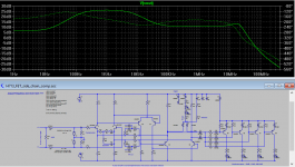
Experimentation with P and N versions spliced for common mode distortion cancellation produced some interesting results. A general purpose preamp seems viable with the capability to drive headphones. Two versions are attached. The desktop version delivers class A up to 1V RMS into 32R which is near live band levels for a lot of phones. Class B is then available for brain mincing. Distortion is indicated at below 0.001% at 20Khz, with still reasonable figures up to 500KHz. At higher impedance loads, the distortion plummets.
Open loop bandwidth is beyond 100KHz and feedback is around 20dB. The input bases are self biasing , no resistors needed. The design is self protecting and to a degree also protects the headphones. Gain can be switched in if required. The number of devices can be minimized with dual transistors. A practical version could be very compact.
A lower quiescent current version could be used as a portable device.
Attachments
An idea for a very simple one control compressor. Two additional transistors drive a LED which is coupled to a cadmium sulfide photocell. This forms the gain control which can be switched in, in parallel with the gain pot. There is a quirk in this approach. The photocell attack and release times are asymmetrical. In this case, the attack time is slower (LED getting dimmer). However, photocells have hysteresis that evens out changes which might make the configuration usable. A follow up would be to use a side chain based on this approach and implement an attenuator in a manner similar to the LA-2A. The LED would then be reversed and the cathode connected to the negative rail with the anode driven by the emitters.
Attachments
Last edited:
From the LA-2A mold, a side chain compressor. Some additions are present. HF boost or cut for keying, with turnover via selection of caps. A dual-gang control is needed for HF cut. The zener for the compressor LEDs is chosen so that with no input, the LEDs are just off. Additional diodes could be switched in series with the zener, so that compressor action is prevented until a certain level is reached. The slope control adjusts the brightness of the LEDs.
The side chain is parallel with the mic amp sharing the same input. The compressor LEDs and zener can be adjusted so that more LEDs can be added. This is to allow a variety of LDRs which may need to be paralleled due to high impedance of some photo cells.
A LED headroom meter is thrown in. The LEDs are not entirely hard switch on, but should be usable. The good thing is that no currents are pumped into ground.
Attachments
Last edited:
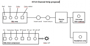
This is what we have so far. Leaning towards passive eq due to amount of R&D effort and ease of build. Unless some one comes up with a brilliant plan. As far as the modules go, fixed configurations may be useful for novices. What these design exercises have shown, is that an SMD uncommitted PCB with just transistor pads is useful because it can be populated with P or N, with a module on both sides. Therefore a two-sided module could be:
1. Dual channel
2. One channel + side chain
3. P and N for the distortion cancelling version
One module covers multiple functions because the transistor footprints don't change for P or N. The module could be edge mounted, or like a big DIL.
1. Dual channel
2. One channel + side chain
3. P and N for the distortion cancelling version
One module covers multiple functions because the transistor footprints don't change for P or N. The module could be edge mounted, or like a big DIL.
Attachments
Color controls may or may not get implemented into the desk- we shall see. I still have to find time to play around with that circuit, but at the moment I've got family in town, and that is consuming a lot of the time that would normally get dedicated to projects- so progress is slow but steady.
I'm definitely going to make a hybrid IC around this, since I think that's about the best way to utilize a versatile circuit. I have yet to test the FET version, mostly because I forgot to add the 2SK3557 JFETs to my cart last time I ordered from mouser.
It will be a full channel strip- ultimately. My next step with this project is going to be to build it into a line stage (great use for some of the remaining rev. 1 boards with the miswired pad switch) and a 4 channel 1u mic preamp. I think before I put much more energy into this design, I want to see how it performs in the real world. Simulations, bench testing and time on the AP box is all well and good, but if it sounds like dog dung, what exactly is the point? real-world testing of a line-stage module looked great. Distortion generally stayed below .009% for all reasonable output levels. I consider that to be respectable. The line stage won't have an input transformer, but it will have an output transformer.
I think I've tracked down a usable chassis for the 4 channel 1u mic pre, and I should have something laying in storage for the line stage. Progress is being made, ever so slowly. Am I the only one who never has fewer than three or four projects going at once?
Depending on if I can learn how to do so, I may try to design my own input and output transformers for this thing as well- that's a little down the road.
Also, my order of 10 Rev. 2 boards came in today, and they look reasonable. Now I've got to actually build something with them.
H713
- Home
- Live Sound
- PA Systems
- Solid-State Balanced Microphone Preamplifier