Not really sure if this is the right category to post this in- let me know if it isn't.
I'm currently modifying (redesigning) a Sony MXP-2900 mixing console. This is really my first try at designing a microphone preamplifier, so I'd like to get some feedback on my schematic. This is designed with studio usage in mind, and will most likely run off of +/- 18V rails, though I would like to make it usable from +/- 16V (500 series rack) up to +/- 24V (what this console will ultimately use for power rails when it's complete).
Notes:
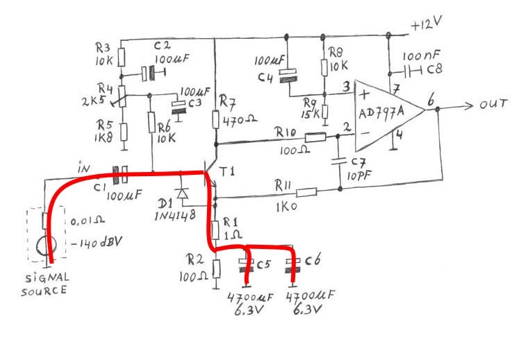
The input transformer is just a 1:1. I don't see any reason why a JT11P-1 (line input transformer) couldn't be used for a microphone input. Technically this is not necessary, but it improves the CMRR and immunity to RFI. Output transformer is optional as well.
-When I prototype the circuit, I'll try both the BC550/BC560 transistors as well as the KSC1845/KSA992 transistors and see which results in lower noise and distortion.
I'd really appreciate it if I could get some feedback, as I've never designed a mic pre before, and it is certainly a bit of a design challenge.
I'm currently modifying (redesigning) a Sony MXP-2900 mixing console. This is really my first try at designing a microphone preamplifier, so I'd like to get some feedback on my schematic. This is designed with studio usage in mind, and will most likely run off of +/- 18V rails, though I would like to make it usable from +/- 16V (500 series rack) up to +/- 24V (what this console will ultimately use for power rails when it's complete).
Notes:
The input transformer is just a 1:1. I don't see any reason why a JT11P-1 (line input transformer) couldn't be used for a microphone input. Technically this is not necessary, but it improves the CMRR and immunity to RFI. Output transformer is optional as well.
-When I prototype the circuit, I'll try both the BC550/BC560 transistors as well as the KSC1845/KSA992 transistors and see which results in lower noise and distortion.
I'd really appreciate it if I could get some feedback, as I've never designed a mic pre before, and it is certainly a bit of a design challenge.
Attachments
a mic input transformer needs proper shielding and be of humbucking design such that external magnetic fields are cancelled in the dual winding structure of primary and secondary. and R-C series load on the secondary reduces ringing of the leakage induction.
the 50k resistor is closing a loop of 2 inverting stages-> instability ?
the 50k resistor is closing a loop of 2 inverting stages-> instability ?
R13 and R16 provide positive feedback rather than negative feedback, is that intended?
Due to the thermal noise of R9 and R10, with everything else noise-free, you already have a 4.5 dB noise figure for a 200 ohm source. No big deal when people are shouting into condenser microphones from a short distance, but it could be an issue with soft sounds and dynamic microphones.
If you intended negative feedback, maybe you could take the feedback to the emitters and replace R9 and R10 with lower values, or with lossy ferrite beads.
I would definitely add anti-parallel diodes across the base-emitter junctions of the transistors, especially the input transistors. A large transient, like you could get from connecting a microphone with the phantom supply on, could cause avalanche breakdown in the base-emitter junction, which tends to cause a large increase in 1/f noise.
The output transformer may need AC coupling, right now any offset at the amplifier's output will saturate the transformer's core.
Last edited:
Use ZTX851, they are the best available for ultra low noise.
The trend in microphone preamps is going transformer less.
This paper http://www.thatcorp.com/datashts/AES129_Designing_Mic_Preamps.pdf
is great, it explains the reasons for the front end circuitry and explains 3 typical and good designs.
_Simple Mic Preamppage 27. It is easy and give good results.
_Complementary Feedback Pair Mic Preamp page 35. Is better.
_Current Feedback Instrumentation Amp, page 45. My favorite. There is no need for the two constant current source. About this topology you can find details looking at "Monte Generoso Samuel Groner" and "Double balanced Graeme Cohen".
for low source impedances a transistor with low base resistance is best. traditionally PNP transistors with 'N' base material have a lower base resistance.
yet transistors engineered for HF or high currents have also low base resistance. the ZTX851 has a base resistance of 15milliohms according to the spice model.. seems a bit unrealistic to me.
for example a HF transistor like 2sc5065 of my favourite brand performs very well.
yet transistors engineered for HF or high currents have also low base resistance. the ZTX851 has a base resistance of 15milliohms according to the spice model.. seems a bit unrealistic to me.
for example a HF transistor like 2sc5065 of my favourite brand performs very well.
The ZTX851 noise has been measured and compared with other transistors. This is far more dependable than Spice models.
Ultra low noise amplifiers
ZTX951 a PNP is lower noise but lower gain. Could be used instead of ZTX851, but not worth it.
Ultra low noise amplifiers
ZTX951 a PNP is lower noise but lower gain. Could be used instead of ZTX851, but not worth it.
R13 and R16 provide positive feedback rather than negative feedback, is that intended?
Due to the thermal noise of R9 and R10, with everything else noise-free, you already have a 4.5 dB noise figure for a 200 ohm source. No big deal when people are shouting into condenser microphones from a short distance, but it could be an issue with soft sounds and dynamic microphones.
If you intended negative feedback, maybe you could take the feedback to the emitters and replace R9 and R10 with lower values, or with lossy ferrite beads.
I would definitely add anti-parallel diodes across the base-emitter junctions of the transistors, especially the input transistors. A large transient, like you could get from connecting a microphone with the phantom supply on, could cause avalanche breakdown in the base-emitter junction, which tends to cause a large increase in 1/f noise.
The output transformer may need AC coupling, right now any offset at the amplifier's output will saturate the transformer's core.
Yes, negative feedback was intended. I'll have to look at the spice simulation, but it looks like R16 was actually supposed to be connected back to Q1 rather than Q2.
I didn't even think about the noise from R9 and R10, but you bring up a good point. I'll try connecting to the emitters and see how it simulates. I'll play around and see what I can come up with.
Also, I'm sure there are better transistors out there, but I'm going to start with the BC550/BC560 and KSC1845/KSA992 because I have them in stock. If the noise performance isn't where I want it, then I can proceed from there.
As a side note, I have some Jensen JE-MB-C bridging transformers that I will probably use at least for the first couple preamps, as well as some JT11P-1 that I can try as well to see what happens. I also have about 16 transformers out of a Sescom mic splitter (1:1 ratio) that could work as well, though given what they came out of they're probably nothing special. I'm fully aware that the current trend is transformerless (especially due to cost), but I think I want to stick with a transformer coupled design for my own purposes.
for low source impedances a transistor with low base resistance is best
...in common-base configuration.
Most of the noise in that circuit comes from the resistances of the transformer windings which are 1.5k or so.The input transformer is just a 1:1. I don't see any reason why a JT11P-1 (line input transformer) couldn't be used for a microphone input.
You'll note Jensen microphone transformers such as the JT-MB-CA have winding resistances of 50 ohms or below. A line transformer winding is designed to have a noise resistance an order of magnitude less than line impedances, microphone transformers have noise resistances an order of magnitude below the microphone impedances.
The classic error when first working with low-noise circuits is to add series resistance to the source - this is to be avoided as much as possible (yes, sometimes you need some for protection purposes. Its a mistake everyone makes!
In general try to keep any series resistances less than the source impedance, so 100 ohms or so max for a microphone input.
Series resistance not only adds Johnson noise of its own to the signal, but multiplies the input device's current noise to a voltage too (in fact even reactive impedance does that, even though it has no Johnson noise)
This paper is clear about what is a ultra low noise amplifier.
Here one for measuring low noise bipolar transistors.
Ultra low noise amplifiers
Figure 1 shows clearly what matters.
Here one for measuring low noise bipolar transistors.
Ultra low noise amplifiers
Figure 1 shows clearly what matters.
...in common-base configuration.
Why? We're not trying to characteristically terminate a transmission line or anything like that. In fact a too low input impedance could overload the internal amplifier of a condenser microphone.
Series resistance not only adds Johnson noise of its own to the signal, but multiplies the input device's current noise to a voltage too (in fact even reactive impedance does that, even though it has no Johnson noise)
What to care for, about the caps that are in serie for phantom power isolation ?
Here's the updated schematic. Interesting point about the winding DC resistances of a line transformer- not something I had really considered. That certainly could introduce noise.
I reconfigured the feedback scheme so that 1) It's actually negative, and 2) I was able to eliminate the 180 ohm resistors on the input. That should drop the noise floor a bit.
As far as the AC coupling to the output transformer is concerned, I'm going to wait until I've had a chance to prototype the circuit to see if it is necessary. I do suspect that it will be, since I won't have perfectly matched resistors and transistors throughout, but we shall see.
Attachments
Please add the antiparallel diodes, you don't want to have the noise floor ruined when someone accidentally connects a microphone while the phantom supply is on.
If they had existed, they would have needed to have relatively large values")
What to care for, about the caps that are in serie for phantom power isolation ?
If they had existed, they would have needed to have relatively large values
With 10Ks at the collectors, you have very little headroom. I would use lower values. I would remove R18 R19. Don't forget 100nF caps as close as possible to power pins at the op-amps.
To see about DC at the output with the simulator you need non equal transistors. A 1°C temperature that decreases Vbe can be simulated adding a -2mV voltage at the base. Or, to decrease Vbe you can make other BC560 BC550 models with a higher IS. To simulate for higher gain you can make transistors models with higher BF.
To see about DC at the output with the simulator you need non equal transistors. A 1°C temperature that decreases Vbe can be simulated adding a -2mV voltage at the base. Or, to decrease Vbe you can make other BC560 BC550 models with a higher IS. To simulate for higher gain you can make transistors models with higher BF.
Last edited:
Please add the antiparallel diodes, you don't want to have the noise floor ruined when someone accidentally connects a microphone while the phantom supply is on.
Wouldn't said diode affect the maximum gain of the first stage though?
- Home
- Live Sound
- PA Systems
- Solid-State Balanced Microphone Preamplifier