The build looks great - Lots of man hours in there.
Interesting to see you are using local regulators.
Are you doing anything special with the LM317 - 337 regulators or are they fairly conventional circuits?
Have been rebuilding a mixer recently (Ecler Sclat) using the Panasonic FC caps and it was surprising how much this reduced the noise floor when running off a bench power supply during testing.
Not that special with the lm317 -337 regulators. We do use a small capacitor on the adjust pint. (10-22µf).
This makes the regulator work much better. don't go bigger then 10-22µf.
On the output we use around 100µF
And also decouple the output and input with 100nF close to the pins.
This way the lm317 works very nice and the noise will be lower then the noise coming from the preamp itself.
And for the opamp stages it's not a problem if you use good opamps.
Ok guys,
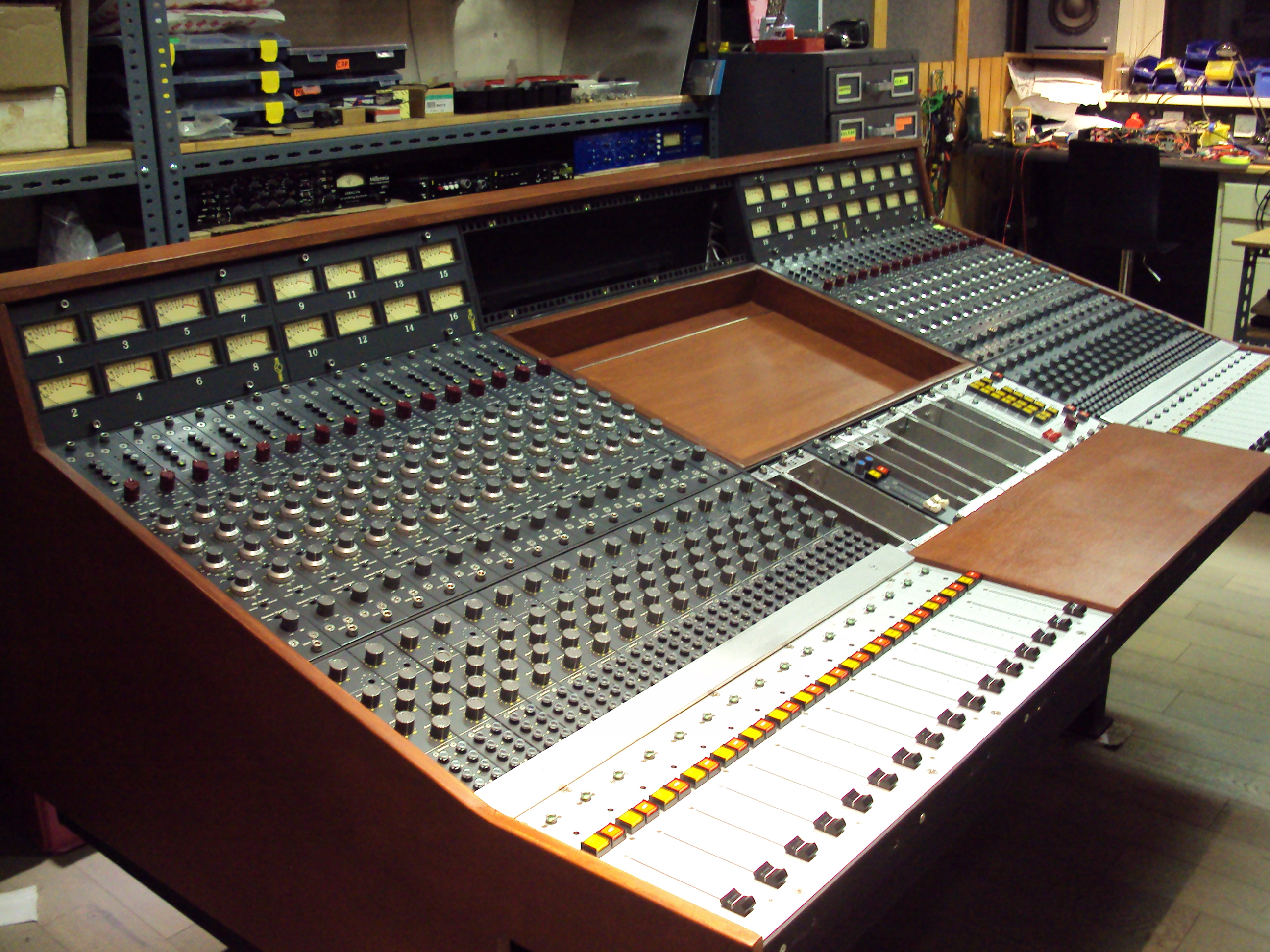
A little update on our console build.
This is where we are now
Connectors that are used to connect the BUS lines together. These are located on the mid section. there is one extra connector for a future expansion.
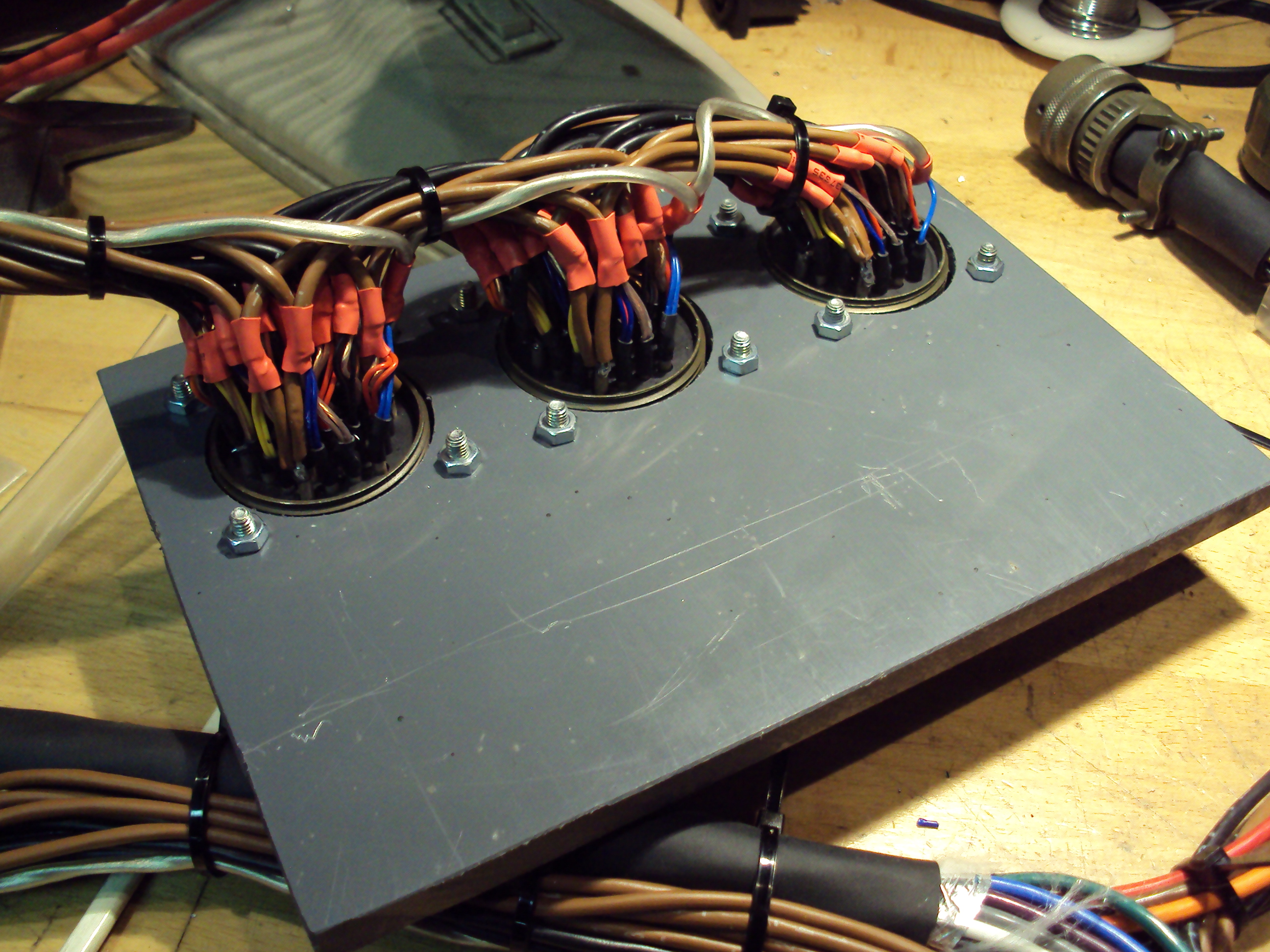
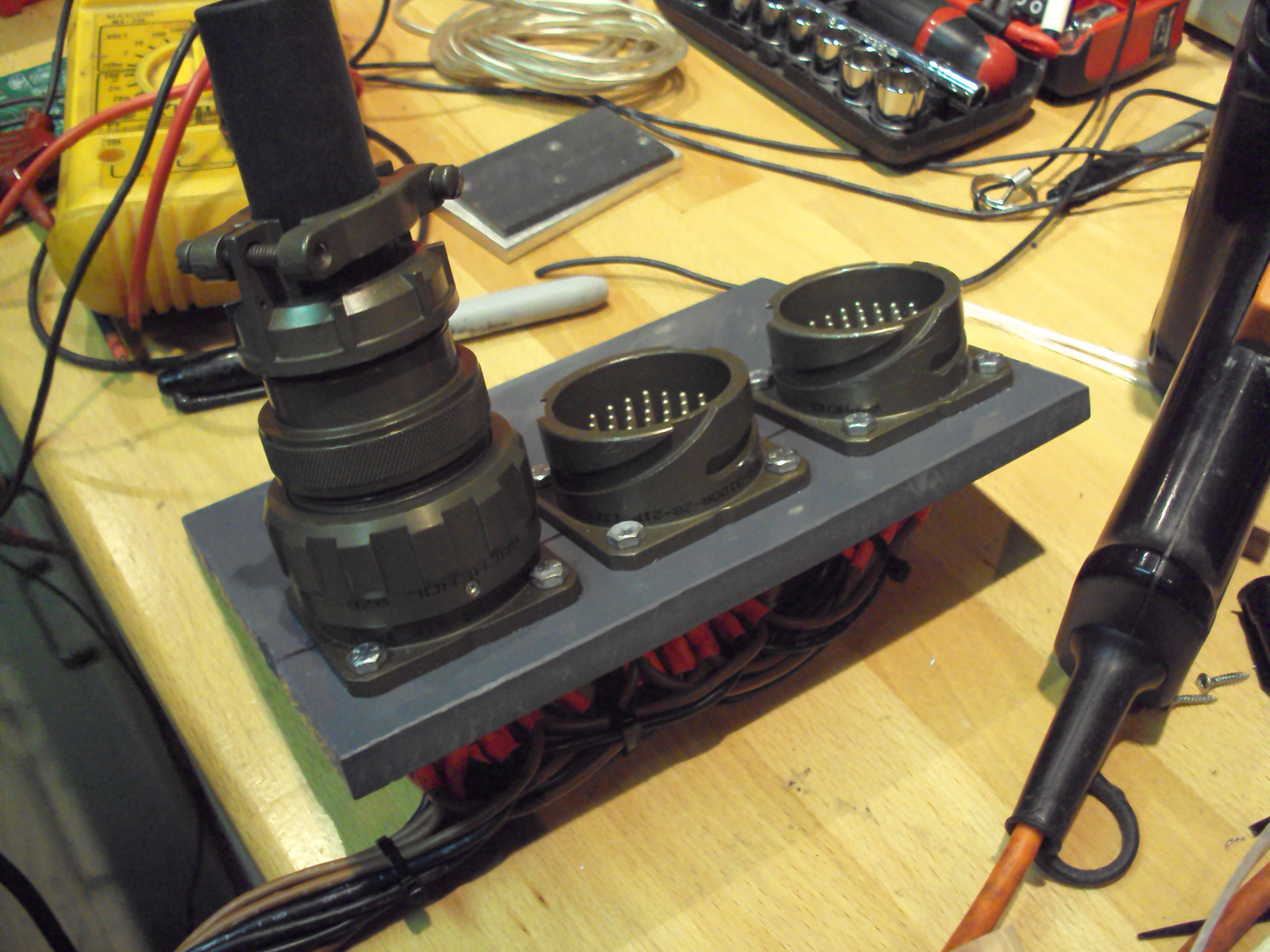
These are mil spec connectors made by amphenol.
This is the cable boom been made for the mid section modules.
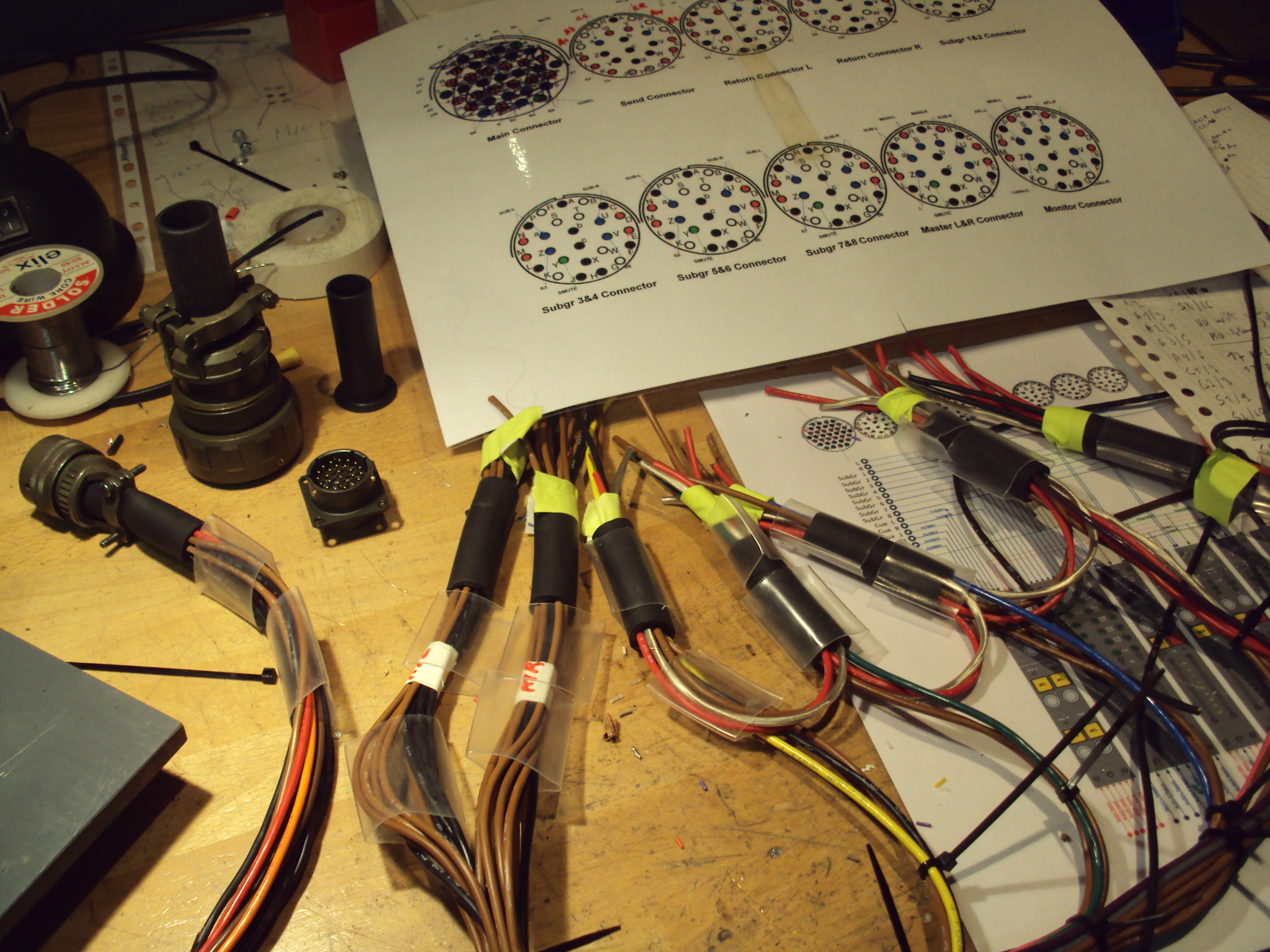
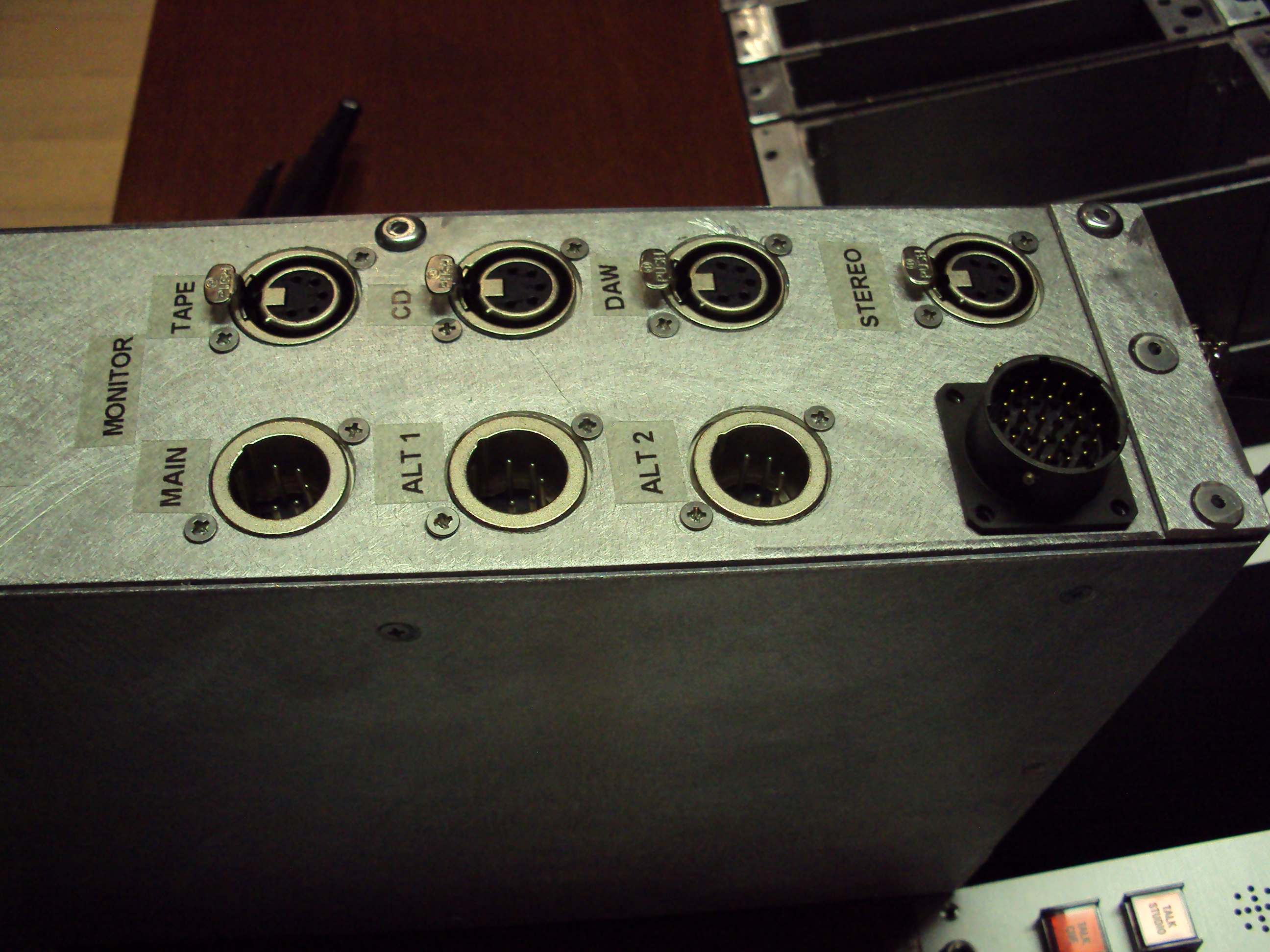
Back of the monitor section.
XLR's are used for external in/out
The rest comes from the smaller amphenol connector
and then here is a small schematic overview of the midsection routing.
http://www.aman-nai.be/console/middensectie.pdf
There can still be small faults/changes on the schematic overview as we go along.
A little update on our console build.
This is where we are now
Connectors that are used to connect the BUS lines together. These are located on the mid section. there is one extra connector for a future expansion.
These are mil spec connectors made by amphenol.
This is the cable boom been made for the mid section modules.
Back of the monitor section.
XLR's are used for external in/out
The rest comes from the smaller amphenol connector
and then here is a small schematic overview of the midsection routing.
http://www.aman-nai.be/console/middensectie.pdf
There can still be small faults/changes on the schematic overview as we go along.
The frontpanels where done by schaeffer. Al the rest of the metalwork we did ourselves (even the channel module cases) The channels are based on the 19" standard.
The mechanical work is amazing! It looks excellent too.
The thing is if you just want a mixing desk for hobby projects it would be cheaper to get some china whatever oem brand product. It will work as intended but it will not last. If you want something with very decent quality however it would be very difficult to find something to begin with and it will be VERY expensive.
[...]
Our goal is to make it last a long time and sound good.
I have deep respect about your craftsmanship. But, well, 'nobody' wants analogue mixers anymore. That's why you can get professional 24/32/48ch mixers from renowned EU manufacturers for below 1000 bucks. And they are built like tanks too. There are tons on the market, many become scrapped because they can't sell them.
You're not done yet and looks are easily deceiving but it looks you didn't plan to go for subgroups?
There are 8 Subgroups ")
And while there are a lot of big mixers on the marker. Most of them are not inline, Don't use the classic neve circuits (all transformer coupled and class A)
And they are build like tanks but we decided to go one step further. (most consoles just use flat cable and subd connectors......we use all screened cable/ mill spec and XLR connectors)
So there is a big difference.
But indeed analog consoles are less used for mixing...
But you still need preamps to track.
The mixer is made with this in mind also.
Last edited by a moderator:
Ok, So it took a while for an update, Just been busy with the consoles. When doing a project like this, you get to learn a lot about grounding etc.... The mixing busses are completely balanced so no grounding issues here. But the summing amps have around 40db of gain. The amplifier stages are single ended class A stages so the routing of the ground is critical. Some of it was trial and error. A tip for anyone is to split Analog ground / digital ground and screening but be carefull to not make unwanted loops. A second tip is to imagine every ground wire/connection as a resistor A third tip is to connect screening only on one side.
So first of I have made a sketch of the summing principle I used.
I could have just use a normal style neve preamp with a fixed gain and keep impedance of the bus constant (voltage summing = passive summing).
On the other hand to avoid pops/clicks and to avoid having the impedance constant it would be nice to use a form of active mixing = current summing
My goal was also to keep the buss balanced to avoid common mode noise
So I came up with the idea of the following schematic.
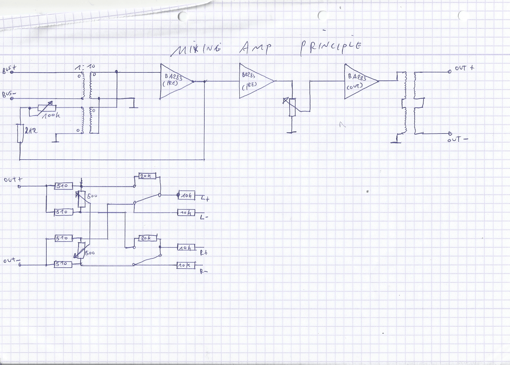
The bus is terminated in a transformer that is coupled to the aplifier stages. the transformer is 1:10 but using the secondary in parallel it's 1:5. This way the impedance of the bus is a better match to the input transistor(noise) "BA283 pre" means the preamp stage of the neve BA283 board "BA283 out" means the output stage of the neve BA283 board
the output of the first preamp stage is fed back to the transformer.The coil of the input is the same ratio as the feedback coil. The resistor is added to set the gain. When the impedance of the bus changes the gain of the circuit changes. The frequency response is also linearised. the output capacitor of the ba283 preamp stage is made bigger and the gain of the stage shouldnt be to extreme to avoid oscillation. A capacitor across the secondary was also needed to tame the transformer. My first idea was to use the two stages and have more open loop gain but this becomes unstable. Very low frequency oscillation and sometimes HF oscillation. So I have split the stages. One with the feedback loop and another one with constant (low)gain that drives the fader.
The result is quite good and seems to work. -3db is around 60kHz with 40db of gain.
The second part is only used on the buss mixing amps and is used for routing to the L/R mixing. It's a balance control and an L/R switch.
Now some more pictures.
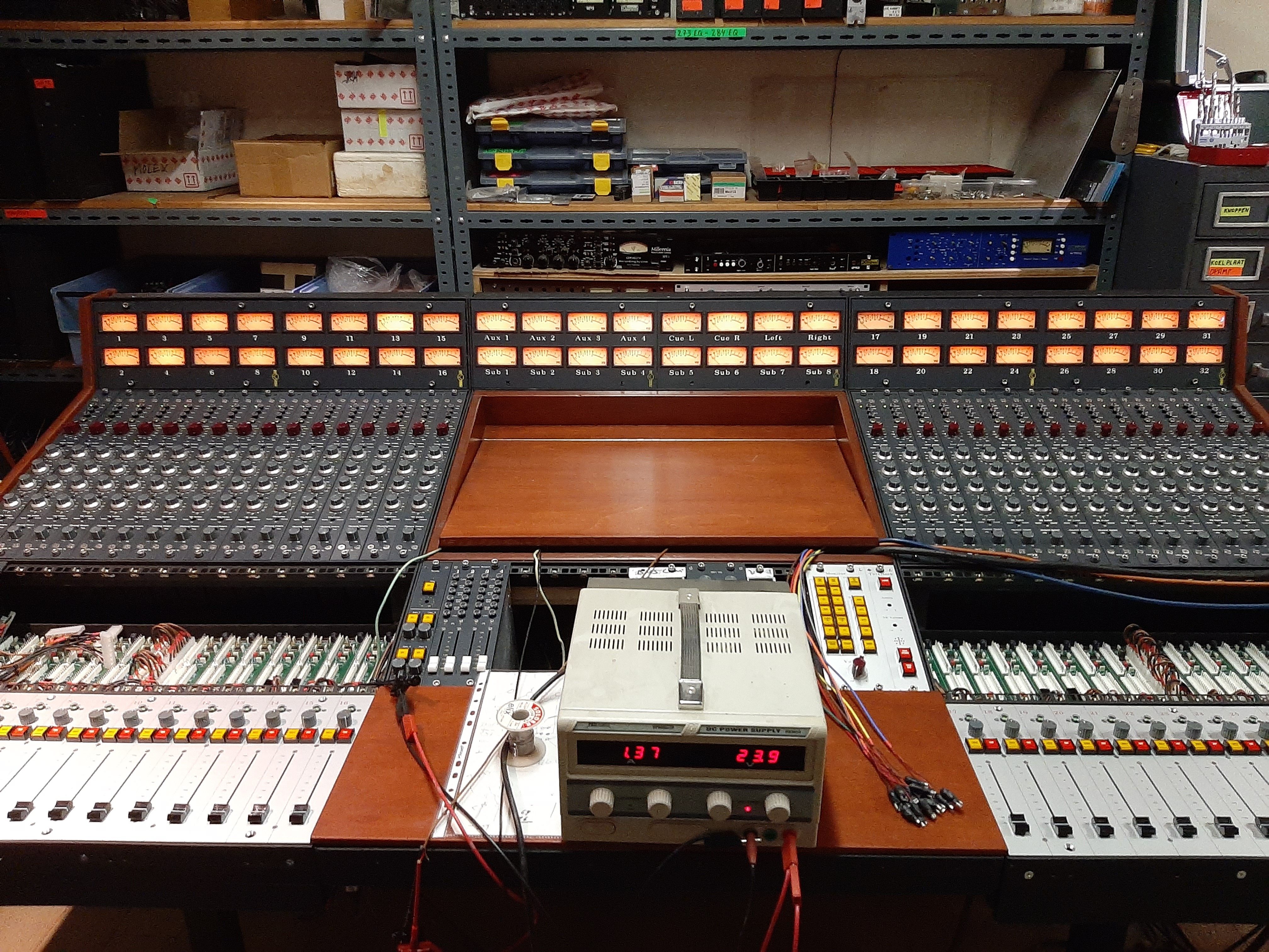
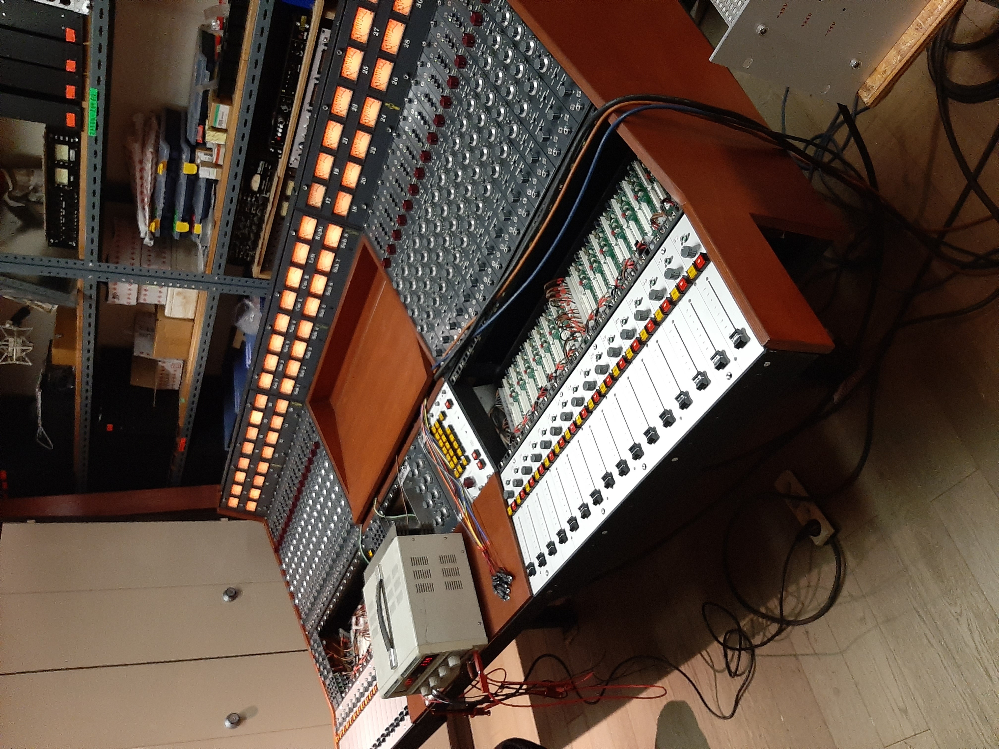
This was during testing of The VU lights. That's why we had the lab supply for checking.
That's it for now. We are getting closer to completing this desk. Hopefully in a week or 2 I think
So first of I have made a sketch of the summing principle I used.
I could have just use a normal style neve preamp with a fixed gain and keep impedance of the bus constant (voltage summing = passive summing).
On the other hand to avoid pops/clicks and to avoid having the impedance constant it would be nice to use a form of active mixing = current summing
My goal was also to keep the buss balanced to avoid common mode noise
So I came up with the idea of the following schematic.
The bus is terminated in a transformer that is coupled to the aplifier stages. the transformer is 1:10 but using the secondary in parallel it's 1:5. This way the impedance of the bus is a better match to the input transistor(noise) "BA283 pre" means the preamp stage of the neve BA283 board "BA283 out" means the output stage of the neve BA283 board
the output of the first preamp stage is fed back to the transformer.The coil of the input is the same ratio as the feedback coil. The resistor is added to set the gain. When the impedance of the bus changes the gain of the circuit changes. The frequency response is also linearised. the output capacitor of the ba283 preamp stage is made bigger and the gain of the stage shouldnt be to extreme to avoid oscillation. A capacitor across the secondary was also needed to tame the transformer. My first idea was to use the two stages and have more open loop gain but this becomes unstable. Very low frequency oscillation and sometimes HF oscillation. So I have split the stages. One with the feedback loop and another one with constant (low)gain that drives the fader.
The result is quite good and seems to work. -3db is around 60kHz with 40db of gain.
The second part is only used on the buss mixing amps and is used for routing to the L/R mixing. It's a balance control and an L/R switch.
Now some more pictures.
This was during testing of The VU lights. That's why we had the lab supply for checking.
That's it for now. We are getting closer to completing this desk. Hopefully in a week or 2 I think
I'd like to preface this by saying that I am generally an objective person- I don't believe in premium capacitors or single-ended triode "magic", I consider the 845 to be a fairly useless tube, and the numbers from an audio precision mean a whole lot more to me than some "listening expert" giving it the thumbs up.nice build and much work. But I still do not see what those strange "neve" bipolar circuits can do better that just some standard low noise audio OPAMPS.
Nobody claimed that a Neve console had the lowest distortion. "On paper", so to speak, it's better to use low-noise, low distortion op-amps. For a live show, this is the way to go.
But this is not a desk for live sound. Nobody tours with a Neve console- it'd never hold up, they're too heavy, and they aren't really laid out for live sound. Back in the 1970s, the 80xx series of Neve consoles were pretty much the creme of the crop for use in a recording studio.
In a studio, you are trying to create a sound, not reproduce one. The cleanest, lowest-distortion device is not necessarily the best. Neve consoles are certainly not the lowest distortion things out there- far from it. Despite, or perhaps because of this, more hit records have been recorded through Neve circuits than probably any other. The famous Neve 1073 preamp is arguably the greatest microphone preamplifier ever designed- certainly the most famous. Other legendary consoles like the Trident A-Range and the EMI TG12345 followed similar formulas.
Great desks have been built with low distortion op-amp topologies. The Focusrite desk immediately springs to mind. A lot of it depends on what you want.
So on paper, a NE5534 is great. It's going to produce the lowest distortion and probably some of the best noise figures. But unlike in the listening room or in a concert hall, in a studio what counts is the sound that makes it onto tape. At least in my book, the one area where subjectivity gets a pass is in a creative environment.
Ok So indeed it's not exactly like a virtual ground bus.
Because of the feedback I would say "virtual zero impedance" but I could be wrong at this.
If you leave out the transformer.
make the amplifier stage inverting and put the feedback on the bus.
Then you change the balanced bus by connecting the negative to GND and what you have now is a sort of virtual gnd summing bus.
Ok so about the neve circuits. I was always very objective about this and then I build a neve 1073 and used it when recording and for some reason it just works...
I also had a chance to measure with an AP analyzer and the distortion is not really that extreme.... in the midband I have measured 0.005%. It goes up a little at the high end (10kHz +) 0.01% or something but this depends a lot if you use tantalum coupling caps or not. I would say avoid those things as they don't have any use in audio. This is debated and discussed a lot but I don't use them (original neve used them I think) and the result is that it sounds more open then the "original" so no tants for me.
In the low end distortion rises because of the transformer coupling. And I think a great deal of the sound has to do with this. Especially the output stage with a bias of +/-80mA flowing trough the primary.
However it can do 26dbu+ in 600ohm.
The distortion rises to around 0.5% @20Hz and +4dbu
Some people say the distortion in the lowend generates subharmonics and can make a vocal sound like it has more body.
However I don't have really proof of that.
What is also important is the kind of harmonic profile the distortion has.
2nd harmonic is the highest and it goes lower with every harmonic. Not many high order harmonics are there.
There is a lot to think about and to tell about these circuits. They are not perfect but not that bad either...
Just to say for insert sends and returns we did use some opamps and that chips.
The idea is to keep the inserts very transparant.
Still busy on the last bits to finish the console....
For the power supply we used 24v transformers with 2 outputs so you can make a center GND and a symmetrical power supply.
So we started from rectified 24v ac (3phase rectifier), so we have a raw supply of around 30-32v.
this comes from the big power supply in a different room.
In the console there are smaller power supplies that make this into stabilized +24 and -24 Vdc. for audio and +24Vdc for auxillary supplies.
All using LM317/LM337 regulators
This together with 48v phantom is used to power the different modules using a 5pin XLR.
Two channels for one smaller power supply. If one power supply fails only 2 channels are out.
Having +24v and -24v gives us al the freedom what to use in the modules.
+24vdc can directly be used for the neve circuitry.
For the opamps we can use +/-24vdc and make it into whatever we like.
I normally use around +/-15vdc if there are lm324's for the signal led's as they can't take more then that according to the datasheet. (I did by accident used them at 18v once and they stayed working but I wouldn't recommend that).
If there are only opa604 opamps and that chips I normally go to +/-18v. It gives a little more headroom although maybe it's not a big difference.
So the ideal way is to have a 24vdc and have a symmetrical power supply of around +/-12vdc to +/-18vdc. That way the GND reference is the same.... Works easier most of the time.
Opamps don't mind the difference and the sound shouldn't be any different also.
You could also put -v of the opamp to gnd and +v of the opamp to +24vdc.
The opamp won't really notice the difference.
However you need to put 12v offset to the opamp using resistors.
If you had a symmetrical supply you can just use the GND reference.
And if you use switches etc you need to see where the input resistors are referenced to. otherwise you could get problems with loud pops.
For example the output of an opamp sits at 12vdc. Then there is a capacitor coupling this to the input of a transistor stage.
That input is referenced to GND using for example 120kOhm. before going trough a capacitor to the transistor stage.
So if this is connected there will be a loud pop when the capacitor is charged. After that there will be no problem.
Now if you add a switch and you open the switch and close it again there will be a loud pop again.
The solution is to add a resistor from the capacitor at the output of the opamp to GND.
The other way around is also possible and more confusing.
If you had a +/-12Vdc supply and you want to use a (neve) transistor stage you could just connect the "GND" of the transistor stage to the -12vdc and the +24 will go to the +12vdc.
Now when you switch the output of the opamp to the input of the transistor stage there will be a loud pop so now you have to reference the output of the opamp to -12vdc using a resistor after the output capacitor. OR you can change the reference of the input resistor from the transistor stage to GND.
I Had to do this once when I only had space for a symmetrical supply combining some API2520 based preamp with a neve 1073 EQ stage.
It is just a question where the GND reference is
Personally I would take the easy route and just use some extra power supplies when possible and have the same GND reference.
Start with a 24v transformer. Then use a lm317 for 24vdc an extra lm317 for +12 to 15vdc and an lm337 for the -12 to 15 vdc. It's easy and saves a lot of hassle.
I think they did this trick of using the symmetrical supply to power discrete transistor circuits on the 500 lunchbox format but I could be wrong.
I am not a fan of this however (not a fan of the 500 lunchbox format either...)but it shouldn't affect the sound.
24Vdc is 24Vdc and if the GND is reference in the middle, at the bottom or even at the top it shouldn't matter for the sound.
It's just the practical side of things.
In a few days there will be some more pics of teh console if I can find the time...
So a small update
We added A peak meter based on russian IN13 nixies.
Log conversion is done using the detector of the that4301 chip (has been obsolete since a few months....)
minimum is -35dbu and maximum is +25dbu which the output of the desk will provide in 600ohm without any problem.
In normal line loads of around 10k it goes up to around 28dbu. More then enough to severe overload some computer interfaces.
you can find a small movie of the peak meter in working at the the facebook page of vintage audio projects.
I hope the link works.
Vintage Audio Projects
- Home
- Live Sound
- PA Systems
- Custom Build Mixing Console