i have to wonder ,the diodes going through the lil heatsink holes.How do they not touch the heatsink?The insulation can only go so far down .Is it a matter of keeping the leads perfectly straight?.I wonder if im having a problem with that.
All outputs and drivers and pre drivers test good band micas are on the four drivers but i had 80v dc on one side.Like i said then i took all outputs out and drivers and predrivers and they test no short.Im stumped
All outputs and drivers and pre drivers test good band micas are on the four drivers but i had 80v dc on one side.Like i said then i took all outputs out and drivers and predrivers and they test no short.Im stumped
You can test that your diode stack in the predriver emitter legs is not shorted to case ground (heat sink) by looking at the voltage. Should oscillate at the music frequency, and pulse with the beat if your radio source is tuned to a rock & roll station. This is on an analog AC voltmeter, not on a DVM which averages readings over some seconds. I didn't have trouble getting the diode leads to not touch on my blown one, it is a .200" diameter diode with .015" diameter leads.
I found that output transistors drivers and predrivers that passed the double diode test with a meter, once stressed by a OT meltdown, could still fail at rail voltage. Meters test at 2 v typically. A Vceo test is necessary to sort out the bad transistors. Revised test method, I had a 12 v car battery charger, put a e-cap in parallel, put a 47 k resistor on the output, then tested transistors C to E with the base disconnected. The ma scale of the dvm was put in series. Current of a few microamps, transistor is okay. Current of 12/47k, the transistor was bad. Before I put a room heater element in series with the AC input, output transistors that passed the double diode meter test would fail one at time, blowing the tops off which bounced off the ceiling sometimes.
It helps on the DC out side to figure out which component is the first to produce the DC offset. Then poke around there with the meter to look for stupid voltages. Like for example a capacitor with the same DC voltage on both sides. Or a resistor where the voltage drop across would burn it up due to the wattage rating.
In my case the final DC causing source was the input op amp, only sometimes. The channel would play music fine (FM radio source) for a while but when I touched a certain pin with the meter, bang! 170 v on the output. Turns out the solder joint on the op amp socket was dodgy on the minus input to the op amp. That unit had several techs go into it to try to solve the problem, had a very professional label on the back "DO NOT USE CHANNEL A". As a complete amateur, I'm more of a thorough repairman than the pros. I'm not making money at it and don't take shortcuts, or just charge the usual suspects.
When doing this test music to DC test, it helps to have two big e-caps back to back in series with the speaker. When the unit crashes into DC out the speaker pops, the music stops, then a faint hiss.
As I said, unless you are married to DDT (which is for limiting the damage caused by guitar crunch pedals) and VI limiter (which I think is obsolete), you could replace the driver board with a LM3886 variety. You'd need a special +-35 v supply for that, regulated down from rail voltage. Then I'd preserve the op amp input so that twisted pair cable could still be used on the 3 pin input connectors which allows common mode noise (hum) to be eliminated. You'd then have a diy amp. As for VI limiter, four rail protect fets could replace it, two per channel. If the voltage across the FET is too high, a speaker or 1/4 phone plug has shorted, initiate protection shutdown which turns off the FET and lights a red LED on the front panel.
Last edited:
This is with both sc187,s removed.
Now the driver card that was on when the 80v struck has a shorted 6534 transistor.Havent checked it all yet.Maybe that caused it ,havent looked into it again yet.I dont know whats open yet because the resistors are in circuit.Some resistors measure megaohms but not for sure till i lift a leg on em all .no diodes on that board are shorted.that i read id diode test mode.
Now the driver card that was on when the 80v struck has a shorted 6534 transistor.Havent checked it all yet.Maybe that caused it ,havent looked into it again yet.I dont know whats open yet because the resistors are in circuit.Some resistors measure megaohms but not for sure till i lift a leg on em all .no diodes on that board are shorted.that i read id diode test mode.
Last edited:
I don't ever lift a leg on a resistor. Too much work. I do measure them two ways to see if a diode or transistor somewhere is parallel. If so, one way resistance will be higher than the other, and closer to the nominal value. Of course if a resistor reads above its nominal value, it is blown.
I use MPS8099/8599 or MPSA06/56 for the TO92 transistors. 2n5401/5551 will work but they are more expensive.
If the base line overvoltage blew through the drivers to take out a predriver, the op amp is suspect, too. Those will read as a short between 1 and 2 or 3, etc. They're socketed so easy to pull out. On the PV-1.3k when the sound op amp went, that channel the J174 and the op amp driving it blew too. The previous owner must have been hard heads about pushing the breaker back in over & over again after it blew the first time.
Last edited:
Again, I think your semiconductors were stressed by the output transistor failure & rampaging voltage out the base line. You can stress them again with the Iceo test at 12 v or higher as I said in post 62. Else they may fail again randomly. The diode check of your meter at 2 v is no indicator of a good part once it is damaged. PIty you can't buy a 22 v battery ohmmeter anymore, those went the way of the dinosaur. Don't check b-e of any semi with voltage over 6, they are not rated for it. The collectors of OT's are rated 250 v, the drivers 100 v. The predrivers 40 v.
The op amps are only 15 v parts and I've not found any that read okay at 2 v (meter check) and not with regular voltage. I did find OT's & drivers that would stand off 2 v and not 12 v.
The op amps are only 15 v parts and I've not found any that read okay at 2 v (meter check) and not with regular voltage. I did find OT's & drivers that would stand off 2 v and not 12 v.
Last edited:
Will this amp run if i put four new drivers and a pair of output xsistors per side for testing.And of course follow with four new pre drivers as a start to test without driver cards on it?And of course id replace the diode string.I have a bag of 25 4003 diodes.My micas are good still for the 4 drivers.I,ll check em for cracks.
Also when i had it powered for a bit,all outputs were cold,stayed cold,like i had no bias but 80v was on em like normal.
Also when i had it powered for a bit,all outputs were cold,stayed cold,like i had no bias but 80v was on em like normal.
Who knows? with damage so deep it took out a predriver, what else is damaged?Will this amp run ?
Yes, you can run with one pair of output transistors.
No, shotgun replacing everything is standard practice, but often misses a lot. All the outputs have to change on a channel if one blows, but ahead of there I limit my replacement to what is damaged. You can see some things with the 12 v Iceo test I keep talking about, which is a sort of 12 v ohmmeter test for collector junctions. But other than that, powering up the amp on an AC current limiter and poking around with the voltmeter looking for stupid voltages is my favorite technique. I found blown op amp rail bypass caps that way, which are not usual suspects. As far as changing the diodes, having them is nice, but if they are not bad why do that work? You can read the voltage on the diode stack between pins 3 & 11 of the interboard connector, why not try that with the unit powered up to see if the parts are okay? It should be between 2.4 & 2.8 v. Warning, no jewelry on hands or neck, use a clip lead and one hand, never probe a PA amp with two hands, current across your heart can stop it. This amp has lethal voltages if you use two hands. Pamona grabbers are nice.
You can tell a lot with a DVM, but for other blown things an FM radio to provide music, and a $30 analog VOM with a 20 VAC scale and a 2 vac scale are a lot more productive than a scope IMHO. You have to put a .047 capacitor in series with the ground probe on an analog vom to make it read AC only (elseit will false indicate on DC voltages)
Cold output transistors, yeah, Peavey are made to run full out, and may not have the lowest crossover distortion of a Mark Levinson or Parasound at 2 watts. I dick with the diode stack on mine to eliminate the crossover distortion at 2 watts after everything is working, since I listen at 2 watts a lot in my house. Voila! hifi amp, not a PA amp. An hour of tweaking and maybe one $.07 resistor inserted in the diode stack. The cs800x came from the factory with low full wattage distortion, but after we put non-factory selected transistors in, who knows where the cold distortion level is? I put cinch solder terminal strips in to make test points on the emitter resistors so I can read idle current with the boards inserted and powered up.
Last edited:
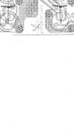
the dual diodes i may have put in the wrong place.Are both of these 13886 diodes actually on the heatsink in a loop like the 4003 ones are?I saw in another forum that the heatsink only has 1 dual diode there in a loop and the other is somewhere else .Before i mess with it again i wanted to know specific location or where they are .i,ll post a pic of where i put them.Maybe i got it wrong.I had them in the heatsink at the end across eachother but in series.Again thanks for yalls help.Im still not a veteran like yall.
Can i start by putting my four to3 drivers in and put just a pair of outputs for each channel to test?Will it work that way if i get the driver cards fixed,or does the cards need them all there to derive voltage from?
I installed the two double diodes as shown on the schematic phot rientation wise also .Was i wrong?
Can i start by putting my four to3 drivers in and put just a pair of outputs for each channel to test?Will it work that way if i get the driver cards fixed,or does the cards need them all there to derive voltage from?
I installed the two double diodes as shown on the schematic phot
rientation wise also .Was i wrong?Attachments
Last edited:
I,ll update later,i have my kids here.I know i havent followed everything yall have said.But im trying to understand it one section at a time.I want one side to work lol.Forget the other for now.Deal later with the bad one .Thanks again for all the advice.May give parts to yall later if i cant get it goin.Transformer shipping is high though.Its heavy.
One more question ,i know yall know.Did i lose them or are the 71180/81180 drivers supposed to use insulating washers on the bolts?I know they use mica pads but did i lose the insul washers?
Thanks.
i know i ask alot of ???? 's
Even if i dont get it going i learn alot and know more now from yall.
I fixed a qsc 1400 but alot less complicated in the driver stage .Im proud of that if thats all i get done .
Thanks.
i know i ask alot of ???? 's
Even if i dont get it going i learn alot and know more now from yall.
I fixed a qsc 1400 but alot less complicated in the driver stage .Im proud of that if thats all i get done .
I had a diode in the bias string shorted to the 80v heatsink.I used wire casing to insulate but what happened was a strand in the casing made a short.
my fault.Thats why i had an 80v dc there .
Im still going to try and get it going.I have a 6534 and a couple items blown on the boards but im determined to fix it..
my fault.Thats why i had an 80v dc there .
Im still going to try and get it going.I have a 6534 and a couple items blown on the boards but im determined to fix it..
Enzo seems to be out traveling or whatever. He would know about the washers. My Peavey amps have drivers on different heat sinks from the outputs, so if the driver shorts to the heatsink it doesn't matter. The glass fiber pcb insulates the drivers from everything else. Look and see if that is the case with yours. The BOM has none but it is only for the driver board, and I think the drivers are on the output board for the X. Peavey tends to connect the collectors on TO3's to the pcb lands with the screws, and serrated washers on the nuts.
The only way I know to buy insulating washers is in the kit with the mica washer from newark.
Congratulations on finding the diode shorted.
I think the MPS6534 is in the VI limiter, which is not very important IMHO unless you're running near the power limit a lot. 2n5401 would work but is more expensive. I got a bargain on MPS56 which would also work, also MPS8599. MPS6534 at 60v vceo must be a very cheap transistor, nobody stocks it. At least it is ebc looking at the flat.
I handled any possible shorted speaker problem by putting 30 amp automotive fuses between the rail caps and the output transistor board. They make fuseholders with spade lugs, and those interboard wires are spade lugs, so fitting fuses in was no problem. Not as failure free as a stage amp with a VI limiter, but I'm not getting paid anything to be on stage. With fuses maybe the next time an output transistor blows, it won't take 9 others with it: at $4.50 each.
Last edited:
Thanks ,ya that casing i used works ,jus dont leave a lone strand in it lol.Is using a 2n3906 for the mps6534 ok?And i have some mps8097's not reading right.they read one way but OL the other way when reversing leads to read through the other legs. i should get a diode drop reading like 0.500-0.700.The mps6534 were shorted e to c if i remember .
I have my 80v and 26 off my amp board and the varying diode string voltage from across stake pins 3 and 12 with amp on.it varies fast but it switches fast from 1.6 to 2.6 v .My meter isnt fast enough.I checked other board resistors on power board.all good.No mega ohms.
No 80v swing this time.Driver boards are next ,1 side at a time
Not going to download datasheets on 2n3906 and MPS8097 I can't buy cheaply. Just make sure Vceo is >60 and gain is >90 at 100 ma like MPS6534.
Note substitute parts houses like NTE & NewJersey Semi publish a lot fewer specs on their "replacements" than OEM houses like ON & Fairchild. So having the same number doesn't mean you have as good a part. You have to download whatever brand you have to know what you've got. Why I jumped all over MPS06/56 at $.12, with vceo 80 and gain 100 they would replace about any TO92 transistor. 2n54012n5551 would replace nearly anything but they were $.35 each.
MPS8097 may be bce or even ecb instead of ebc with the flat towards you. See if using one end pin as base makes it pass the double diode test. In that case you'd have to twist the legs around. Make same datasheet check on Vceo & gain. I'm working on a Petersen swell engine where every transistor is bce. Preverts!
Last edited:
- Status
- This old topic is closed. If you want to reopen this topic, contact a moderator using the "Report Post" button.
- Home
- Live Sound
- PA Systems
- Need schematic for cs800 but not s or x. Looks like the x one.