
edit ok its got two 13886.Now i see.The symbol though is shown as a regular diode.I didnt get why they dont picture the symbol as two facing diodes.I see the two 13886 ones here.in pic.This clears my confusion a bit.
Attachments
Last edited:
update .Lifting triacs gave me sound on b channel.No abnormal dc on terminals,good clear sound.I have .380mv on that one.Other side is half wave distorted because of a driver transistor i removed.The je350.So far its looking better.On off triac i bypassed ,its bad.It blew the 22ohm fp resistor between the power blade connector and the orange signal triac wire.No biggie i bypassed to test.I have a mje350 driver coming then ill retest.Two bad output xsistors are removed at this point.On the bad channel that im waiting on the driver for.
check the front panel LED's with your dvm diode scale. Should read about 1.6 v on green. Your meter may not have enough open circuit voltage on diode scale to check double diodes. My craftfman does.
Yeah, the protection triac's often blow, IMHO. I lift the 47k resistor to the 2.2 uf cap until I've hiwatt tested a board awhile, to avoid blowing the triac again if dc occurs. My watt test resistor load doesn't care if dc is on it or not. I put a cut lead in one 47k resistor hole, then when done spot solder the 47k to the projecting lead, meaning I don't have to take the board out to connect/disconnect it again.
Yeah, the protection triac's often blow, IMHO. I lift the 47k resistor to the 2.2 uf cap until I've hiwatt tested a board awhile, to avoid blowing the triac again if dc occurs. My watt test resistor load doesn't care if dc is on it or not. I put a cut lead in one 47k resistor hole, then when done spot solder the 47k to the projecting lead, meaning I don't have to take the board out to connect/disconnect it again.
Yeah, but blown QSC are $200 or so and blown Peavey's are $20 to $60. Works at least right this minute CS800x are running $170 around here. There is not much wrong with the sound of a cs800x or s after you **** with the output transistor idle current current. I'm putting test points in my PV-4c now to check idle bias current with the board installed. This unit has had 5 sets output transistors, to guess from the signatures. I'm adding heatsink fins and reducing the cutoff temp of the snap action thermostat from 100C. I only want 1/4 watt base level for my TV room, maybe peaks of 70 w if they play 1812 Overture.
one question also.Anyone know fore sure of this gate resistor?Mine blew when the turn on triac went bad.Is it 22 ohm or 220 ohm?22 ohm seems low .But hey im not sure.Since it doesnt show a multiplier after 22 does that always mean its just 22 ohm?I know its a flame proof resistor.Thanks for all the help.I may need more.
Attachments
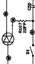
There is no parts breakout for the patch board with the triac on it. However, in 1995 peavey wasn't using 3 digit resistor codes. For example on driver board R119 is shown as 68-1/4W. I would say that means 68 ohms. So 22 probably means twenty-two ohms. I can't look at mine, I have a CS800s and the power supply is totally different. It is a switcher instead of having a transformer.
The big current on the patch bd triac comes at turn-on, when the mains caps are charging up. So BTA25 may be marginal even though you're not using 800 watts all the time. You ought to be able to get these at industrial electrical supplies if you don't want to wait for another box from Minnesota Ft Worth or S Carolina. You'll pay for local stock, though.
If you don't want to pay mouser shipping charge, bta40 is on e-bay. Who knows if it is legit, but the shipping is free. BTA40 700 -TRIAC 700V 40A RD-91 FL, USA. 1pc | eBay
I get a lot of ebay stuff the next afternoon if they found it in stock at Amazon in the county. e-bay seller orders from amazon, ebay seller has Prime, so I get free 12 hour shipping without paying for Prime.
Last edited:
Of course it is 22 ohms. FP for flame proof. WHy is 22 "too small"? It merely limits the gate a little. Look at the other resistors, in the fan circuit for example. 400 ohm, 100 ohm, 2.2k. I think they make it pretty clear.
The schematic calls for a 4025 triac. 400v 25A. A 40A part would be a bit of overkill, though they went to them later. 25A is fine.
I never buy parts on ebay. I am sure there are honest sellers, and some of the parts are real, but it only takes ONCE getting a fke output transistor to blow up an expensive and complex amp, and that wipes out any savings and a lot of the profit from the next boatload of repairs. ebay at your own risk.
True on the ebay parts.I got some fake rubys before.The rattled and were dried up and 1 read 2.0 on my esr and they said USR on them at 105 deg.Ruby never made 105 deg in USR series..I found that out after i got them.
And i wasnt sure about the 22 being 22 ohm.Im still learning alot of this..I usually see an R afterwards.or a symbol.
My good channel right now on the cs800 is 0.03 dc offset and i suppose bias is ok .It warms up but not hot .Runs good no detectable distortion.I have it hooked to a 20watt all in one unit sharp speaker.Tweeter is still fine so i assume no high freq oscillation on good channel.
Yea i know,i dont have a scope to look at the operational parameters.But so far so good on progress.
Thank yall again for the knowledge yall share.
for those that have repaired a cs800x .
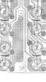
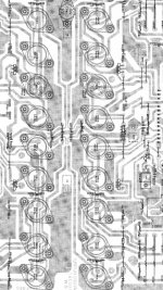
The pic of the layout is this correct layout of the driver transistors on the board?Seems odd that the 70473180 transistors are laid out then the two drivers then two more 73180's .Its different on the 70483180 transistor side ,theyre all together.
I just want to make sure .
I thought only the drivers were the four middle ones on the seperate heatsink.
That layout places two of my outputs on that middle heatsink that is seperate.Just want to know if that print layout is correct.Thanks .
Attachments
Enzo,oh ok.Dam i have them in there like that lol.Well ill put the drivers back like you said,the four in the middle and the 83180 on one side and the 73180 otherside all together ,symmetrical.And the drivers also have a mica insulator under them,correct?Outputs dont.
So it should be 83180 all 4 then 81180 then 71180 next to it then 73180 all four,then other side the same.Dam i sure wouldve smoked it.That seemed odd,im glad i asked.Does anyone have a correct pic of their transistor board or a correct drawing of the one i posted?
Thanks again.
Also that photo you said is a typo ,i got it from peavey.
- Status
- This old topic is closed. If you want to reopen this topic, contact a moderator using the "Report Post" button.
- Home
- Live Sound
- PA Systems
- Need schematic for cs800 but not s or x. Looks like the x one.