What was the tolerance on those caps when they were new? Often you see 18000uF +50% -20% or something like that. You probably have now way of knowing how many uF they had when new. As others have said, measuring their ESR may be more informative as to how well they have aged. You could also go through a reforming process to see what that does. A lot of time and effort though, when you probably just want to buy new caps anyway ")
The fact that the working channel will still out out 330 watts points to caps that are in reasonably decent shape for their age. If they were bad enough to warrant immediate replacement you’d get a lot of hum, low power, or both. Would you want to replace them? Yeah, eventually. But you could certainly wait for a good deal, rather than just paying the $90 apiece or whatever a retailer would want for one right now. So you can comcentrate your resources in the short term on what is needed to make the amp serviceable.
Any DC leakage would add to the capacitance by this method.Hi Folks;
So the caps are both approx .018 Farads ( 18000 uf )
These caps are rated at 15,000 uf, so one could conclude that Peavey amps are like fine wine, they get better with age...........or, as you all have been saying; this test is not telling the full story!
The Sangamo 14m caps that put out 2 watts instead of 100 measured up to 16.1mF but .17 ohm esr.
However even if you can only get 330 watts out of the channels combined, that is plenty for home use. I only play over 100 W out on the front porch on the 4th of July.
I built the 10m replacements for the PV-1.3k out of three 3300 uf caps parallel with 18 ga wire. Sandwiched them between lexan, screwed & glued together, screwed to the rectifier board instead of using the 4 post mount as original caps had. About 1/3 the price of 10mF caps that only had 2 posts.
Last edited:
Hi Indianajo;
Is DC leakage something that could be measured with a basic ohm-meter? I have often thought of adding multiple caps to an amp's power supply rails. In the case of my PL700B, I toyed with the idea of caps in an external cabinet, paralleled with 12 awg or greater wire to the existing caps, but via large 'soft start' power resistors. The resistors would be shunted by a relay with a 2 or 3 second delay....What do you think?
Thanks, Spind;
I just checked; the caps say 15000 uf, -10% +75%. There is no visible indication of leakage. My 'Micky Mouse' time constant method may not have yielded meaningful results, but still, both caps where within .003% of each other. So they are both good or both failing at the same rate! I am now going to investigate "reforming". I have read the thread about this, here at diyaudio. These caps have been powered up recently, but I still want to investigate any possible benefits. I was warned 40 years ago (man, I'm getting old) about the dangers of powering up amps with electrolytics in power supplies, that have been out of service for considerable time. Since then, I have used a variac on those occasions.
Thanks wg_ski;
Yes, new caps would be expensive. I will keep my eyes open for surplus items. One of my Phase Linears (a PL700 rumored to have been used by 'The Who') still has the original caps. I believe this amp is a 1971 vintage. I would like to find caps that are 100 V rated, so they could work in either amp. As you mentioned, the CS800 caps are functioning for now. After a lesson in cap-reforming, I will move on to transplanting a temperature-controlled fan system. Still no ETA on the new output TO-3's.
PS; I have always thought that increasing the power supply capacitor size would somehow (subjectively) increase the amplifier's 'punch' or short-term power capacity, but isn't peak power strictly limited by the rail Voltage?
Thanks again all, Peter
Would you buy your new tires at the junk yard? Yeah, I did when I was 19, but now I buy my rubber parts brand new at a dealer. Aged rubber is dirt. Rubber ages on the shelf not being used.Hi Indianajo;
Yes, new caps would be expensive. I will keep my eyes open for surplus items.
E-caps are sealed with an elastomer. 10000 rated caps, good long life elastomer, 500 hour rated caps, red gum rubber. You can't tell the hour rating by looking at them. Hint, Peavey in the nineties tended to use pretty long life caps, yours & mine wouldn't be as good as they are. (my Wurlitzer organ caps caps are ****, the hammond H100 ones only pretty good for 20 years). I buy surplus wire, surplus transformers, surplus resistors, transistors (from US surplus houses) NOT surplus e-caps.
Your test jig for measuring capacitance reformed the caps.
Dc leakage is the final stable voltage on the resistor divided by the resistance. That is the current the cap takes after it is done charging up.
DC leakage will be different at the 2 v a DVM puts out on ohms scale, versus DC leakage at 10v or whatever your test jig was, versus DC leakage at rail voltage (80 on these?)
I've got a ST120 amp pumping out 70 W on two channels simultaneously out of ONE 3300 uf cap, so I am no fan of overkill on the caps. Peavey seemed to be able to get 1300 W out of four 10m caps. Havent tested that theory yet, waiting to finish DC rail disconnect circuit. My audience isn't big enough to need 1300 W now anyway.
My only point on multiple caps in parallel instead of one big cap, they is a lot cheaper. They fit in my amp okay and wouldn't fly around during setup/teardown since I screwed the cap sandwich to the rectifier board. Can't afford those OEM 4 terminal caps, didn't even ask the price from Peavey.
Hi Peter,
yes, I know that Indianajo has said it yet, but aren't you even contradicting yourselves with
yes, I know that Indianajo has said it yet, but aren't you even contradicting yourselves with
andI was warned 40 years ago (man, I'm getting old) about the dangers of powering up amps with electrolytics in power supplies, that have been out of service for considerable time.
Best regards!I will keep my eyes open for surplus items.
PS; I have always thought that increasing the power supply capacitor size would somehow (subjectively) increase the amplifier's 'punch' or short-term power capacity, but isn't peak power strictly limited by the rail Voltage?
Thanks again all, Peter
The proper amount of capacitance is that which produces the minimum amount of power supply droop under load, where that load is varying at a 20-ish Hz rate between no load and about 4 ohms. It’s pretty complicated actually, but it works out to about 20,000 uf per rail, regardless of the amplifier size. Any less and you don’t get full power down below 40 Hz, any more and you actually increase the loading on the transformer unnnecessarily due to shorter conduction angles. Which causes the voltage to drop more and give less power not more. True it may hold at the unloaded voltage for few milliseconds longer, but that’s not really where “punch” comes from - it needs to sustain for longer than that.
Subjective “punch” is determined more by whether the amp is clipping or not more than anything else. More sustained output capability equals more punch. Two amps may have the same 80 volt rails, and therefore rated at the same power. The one that only sags to 68V on every bass hit will have more punch than the one that drops to 48. And that’s about the difference between the 1kVA iron beast in the CS800 vs. the 300VA lightweight you get in something modern that’s really only “designed” to run at 1/8 power.
Hi Indianajo;
Thanks for pointing out that my 'time-constant' measuring is actually reforming the caps. Using my regulated 24 Volt supply and 10 k resistor, the voltage drop across the resistor was about 90 mV after one hour and 65 mV after 2 hours (both caps about the same). I left one cap connected over night and the V drop across the resistor was just 16 mV. If Ohm's law still applies in Canada, I = V / R = 1.6 uA! Isn't that pretty good? Googling Mallory's spec on a cap that size, 6 mA was the max. tolerance.
I have read that the caps should be reformed using the voltage that they will be used at ( B+ & B- is 81 V ). Can I use the CS800 for this? Just insert my 10 resistor between the bridge rectifier and the cap? AND----Should I use another large filter cap, on the bridge side of the inserted 10k resistor? My thinking is that the reforming would be done by a smooth DC, rather than 120 Hz pulses? ---Any benefit to this?
Hi Wg_ski;
Thanks again for the positive encouragement on this amp project. BTW, I just had a look at the Crest CA18 schematic. This is my LF amp in my 3-way system. "Punch" is almost an understatement regarding this amp. And surprise; There are 12 Electrolytics in the power supply. It has a two tiered, (class H) supply with separate Left and Right secondary windings, bridges, and two paralleled 10,000 uf caps for each leg!
1.6 uA is great not leakage.
Reforming to 80 v with 10 k resistor would ensure they won't explode. At least until the rubber cracks, the water evaporates out, and a short develops.
AndrewT had a very complicated reforming routine with resistors and stuff. I never did that, I just check my caps for leakage with the DVM ohms scale. No leak, holds 2 v and doesn't drop more than 80 mv/sec after coming off ohms, into the circuit goes the cap. Haven't had any newish caps explode that way.
Last cap explosion was a surplus cap bought from Stereo Cost Cutters, the dynaco bankrupcy high bidder. 4 gang B+ cap worked great 4 hours in the ST70 in 1982, turned it on the next day and it blew the fuse. There was a big puddle of cap slime on the bottom of the amp. So the CDE cap was probably a dynaco reject in the parts room. 10 more years on the shelf didn't help anything.
One more cost cutting tip. I DO buy starred electrolytic caps from authorized distributors. These turn out to be caps maybe a year to 18 months old. That means they are past their shelf life, which means in a new system that hammers them to full rated voltage first thing, they might fail. My pre-installation check with the ohmmeter IMHO reforms them to 2 v (anyway) and no problems have occured. The rubber seal is only a year old on those parts, not a serious defect on a cap rated for 1000's of hours at maximum temperature (which is how they test them). Cause I only buy e-caps rated 1000 hours (bad) or higher (better). Mostly 2000 hours up although newark has really cut back on the long life stock, since maybe I'm the only prototyper/repair guy buying them. Pity, I had to re-e-cap the ST70 4 times in 46 years, and that is too frequently IMHO.
Last edited:
Hi Folks;
Moving on, sort of! I see that leakage current at 24 V, after 2 days is less than one half micro amp. (.004 V across 10,000 ohm), so something is happening---probably good?
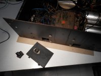
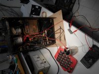
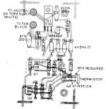
I am going to power up (reform) the caps using the CS800 transformer and the 10k resistor. This requires straightening out the AC wiring mess in this amp. I found a set of schematics with version A, B, and C. This amp has a (Triac) on a steel plate, but not connected in the amp. Only version C has this, and yet this amp does not have the version C pull-out volume controls to engage the clip reduction.
The power switch contacts are rated at 16 Amps. It is a double ganged switch, is there any point to paralleling the contacts? The triac (pictured) had no connections, I thought of re-installing the steel plate, for any shielding benefit for the input board. I don't know how to test the triac, and being disconnected, wouldn't the odds be that it has failed?
Any thoughts on the Triac start circuit? I have had the power switch fail on two Phase Linears, but one of those switches was only rated at 4 Amps.
Moving on, sort of! I see that leakage current at 24 V, after 2 days is less than one half micro amp. (.004 V across 10,000 ohm), so something is happening---probably good?
I am going to power up (reform) the caps using the CS800 transformer and the 10k resistor. This requires straightening out the AC wiring mess in this amp. I found a set of schematics with version A, B, and C. This amp has a (Triac) on a steel plate, but not connected in the amp. Only version C has this, and yet this amp does not have the version C pull-out volume controls to engage the clip reduction.
The power switch contacts are rated at 16 Amps. It is a double ganged switch, is there any point to paralleling the contacts? The triac (pictured) had no connections, I thought of re-installing the steel plate, for any shielding benefit for the input board. I don't know how to test the triac, and being disconnected, wouldn't the odds be that it has failed?
Any thoughts on the Triac start circuit? I have had the power switch fail on two Phase Linears, but one of those switches was only rated at 4 Amps.
Attachments
Peavey used the triac as a power switch to eliminate stress on the real power switch. Also probably allowed them to use a cheaper power switch.
They used the triac between transformer AC bottom and neutral. Turn on surge stresses the contacts on the power switch without the triac. They rectified Ac to DC and fed it through a small resistor to get the 50 ma necessary to turn on a typical triac. The power switch turned on the DC feed to the triac instead of the AC to the transformer.
I've put a CL-150 NTCR between the fuse and the transformer AC hot on my PV-1.3k to cut the turn on surge. It was dimming the lights in the room. Time marches on, components get invented or get cheaper.
Last edited:
The triac doesn’t eliminate the turn on surge - only keeps it from frying switch contacts. If the triac has died then the solution is a bigger triac. One that can handle 600 amps surge current (same as the bridge rectifier). You could design a soft start circuit using a 10 ohm 50 watt resistor, which gets bypassed by the triac after a few seconds. Then you wouldn’t need a bigger triac.
Hi Folks;
Hope to have some time for Peavey puttering over the Holidays. I am reforming the power supply caps at the moment, via a 10k resistor and the CS800 itself. After some research, I thought it couldn't hurt.
The output transistors arrived from Jotrin in Hong Kong. I have heard about counterfeit transistors and wonder if this is a concern with T-03 devices as well. At $2.50 (US) ea., I thought it might be worth a try. Are there any visible indications of authenticity? Seems hard to imagine that these devices were made in Mexico, shipped to Hong Kong, then back to North America---for $2.50 ea US!
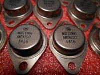
My MJ21195 only say MEX instead of Mexico. They also say BM in front of the date code 1022. I bought this at Newark 12/11 for $3.05.
Short base to emitter, put a 1000 ohm resistor collector to power supply, series an ammeter, hook up to 81 v from the rail caps. Should be nearly zero ma.
Don't kill yourself, use a power strip to turn on after your hands are in your pockets.
On my MJ21195 the mastech capacitance meter (parts express) is getting 720 pf cb and 4780 pf eb.
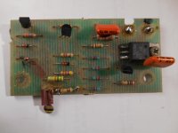
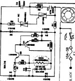
At this point in the project, I would like to add a temperature sensing fan control. I have a cannibalized Tranyor Beta 800 amp (Canadian EH!!) with a 120 VAC fan control. Unfortunately, the pcb has had several components changed and one visibly damaged diode. I shunted the broken 1N4148 'fast switching diode with a 1N4005 (rectifier diode) but the circuit may have multiple issues.
First dumb question; Are 'switching' diodes necessary in this application?
First dumb question; Are 'switching' diodes necessary in this application?
Attachments
Those are 1n4148, about the world's cheapest diode IMHO. I get the fairchild ones for about $.07 in onesies.
Fan circuits got really cheap after FETs got cheap. Get a salvage nfet and a salvage 10k temp sensor from a dead PCAT power supply. Pull up gate to 12 v or something with the sensor, pull down to source (- supply) with more than the sensor cold resistance. Sensor hot resistance should pull fet gate up to >5v.
Fet can drive with drain some power transistor or relay for DC voltage fans, or through suitable buffering (optoisolator) to the gate of a triac for AC fans. Peavey speaker grounds are NOT the same as AC neutral. Triacs typically need 50 ma drive so getting that much current from 120 VAC may take a stage after the optoisolator. Actually with Peavey you might need to cram a wallwart in there for the DC, you don't want to connect switching circuits to the +15 v they use for the op amps. Would pop when the fan turns on.
Edit, I'm listening to Little Steven Underground Garage on FM radio while I type this. Wife went to her Father's, he smokes, Thanksgiving was enough smoke for me. Will play piano for the meal for the poor in the city tomorrow aft. Tried to play for a nursing home today but they didn't want the music to mess up the bingo calls. Ha!
Last edited:
Pardon the horrible resolution. I am determined to get this controller working, it appeals to my character; relatively simple...
Thanks again everyone, for all your advice, hope you're enjoying some Holiday time.
Regards from Peter in Canada
Thanks again everyone, for all your advice, hope you're enjoying some Holiday time.
Regards from Peter in Canada
Attachments
- Home
- Live Sound
- PA Systems
- Peavey CS800 Doorstop to Decent