Hi Folks;
Looking forward to applying all this info to the amp.
Indianajo; I think we agree that a full-complimentary mod is a little 'over-the-top' for this project. My previous speaker system used JBL's small 'Manta-ray' Horns that were commonly used in small theatres and screening rooms. I made a decision to stay as far away from compression drivers as possible when I saw the technical data showing how close in the harmonic distortion was in level, compared to the fundamental. This was a graph rather than a single distortion figure percentage, so it didn't hit me at first, how bad they were.
Here's my next 'brain-burp'; How about building a capacitor checker? I found this at the start of my web search;
"Find the capacitor value by measuring the value of Time Constant
We can find the value of a capacitor by measuring the Time constant (TC or τ = Tau) if the value of capacitance of a capacitor is known in microfarad (symbolized µF) printed on it i.e. the capacitor is not blown and burnt at all.
In brief, the time taken by a capacitor to charge about 63.2% of the applied voltage when charges through a known value of resistor is called Time Constant of Capacitor (TC or τ = Tau) and can be calculated via:
τ = RxC
Where:
R = Known Resistor
C = Value of Capacitance
τ = TC or τ = Tau (Time Constant) "
I am not sure of the math (further investigation required) but I have an electronic timer relay adjustable to 5 seconds or so. Could one measure the attained voltage that a capacitor charges to, through a known resistance, for a fixed period of time, and calculate the capacitance?
Are there other parameters tat should be tested, such as current draw once the cap has reached full voltage---would this be "leakage"?
I hope I'm not getting too far into left field on this, but I understand it will be some time before my outputs arrive. I replaced the "soup cans" in my PL700B, just for ships and giggles, because it was my "pride and joy" at the time. Thanks to all your help on my "Pet Peeve Peavey GPS3500" thread, I built a jig to match output transistors. It would be nice to come up with a way to test big caps, without buying an expensive gadget.
Another quick question; one of the "crow bar?" pcb's located on the output speaker terminals is missing. Any thoughts on just removing the second one?
other than the value the time constant method tells you little about the cap.
EsR is more significant.
the scr (crowbar) that inevitably shorts in case of an output device failure can be dispensed with if your not going to rent the amp to an overzealous DJ and only you can decide if the load you wind up running with this will not be missed when it turns to charcoal!
EsR is more significant.
the scr (crowbar) that inevitably shorts in case of an output device failure can be dispensed with if your not going to rent the amp to an overzealous DJ and only you can decide if the load you wind up running with this will not be missed when it turns to charcoal!
The value of my 1994 removed 10000 uf mains caps was 8300 and 8700. So they were in tolerance +-20%. The ESR was 200 to 400 % high.EsR is more significant.
I finally bought a $40 capacitor meter from parts-express since I cant tell 22 pf from 220 pf just by looking at the numbers. But it won't go to 10000 uf. The Atlas Peak will.
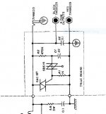
The SCR board protects your speaker and your $100 of new output transistors, what are those worth? it is a 4 part board or five. if you don't want to buy a $1 diac.
From speaker output 47k resistor series 2,2 uf cap (NP non polar or ceramic) to speaker return. Junction those parts goes to input of diac. Output of diac goes to gate of 600 W capable triac (To220 package on little heat sink). Input of triac goes to speaker output, gnd of triac goes to the SAME speaker return as the channel you are protecting. (peavey flying speaker return).
You should be able to build that on Nema CE or LE board (garolite, textolite, micarta), perf board, or wood. Use safety glasses when drilling the holes, #42 drill is what I use.
For diac I bought powerex BS08d from newark. You can alternatively use two 7.5 v zener diodes line to line.
Warning, my triac melted the lands on the board instead of blowing the mains breaker. I installed 25 A rated AG3 fuses in the lines mains cap to output transistor collectors (On PV1.3k). For CS800 use 20 A fuses. Got fuses at oriellys auto parts, they are cheaper than newark. mount clips with spade lugs cost more than the fuses. Spade terminals also from Dorman at Oriellys, AMP (TE connectivity) Panduit 3M Ideal terminals are even better. Crimp terminals from e-bay/amazon/radiosh*** made in ***** are ****, melt at 20 A.
Last edited:
Thanks guys, I somehow gather the crowbar circuit should stay! This amp may be abused in it's future life. I am going to check a cannibalized CS400 to see if there is something I could use.
I will investigate cap testers, a new Flukemeter is on my Christmas list anyway. My Hong Kong trannies (maybe I should re-phrase that) are delayed by a Canada Post strike, so I still would like to investigate a home-brewed tester.
I will investigate cap testers, a new Flukemeter is on my Christmas list anyway. My Hong Kong trannies (maybe I should re-phrase that) are delayed by a Canada Post strike, so I still would like to investigate a home-brewed tester.
Attachments
The assumption is that when the crowbar trips, it is because output devices are already blown. I’ve had a PL400 do this, and of course take out the speaker.
However, there are other reasons that an amp can put out dc, and you don’t want further damage. I’d junk the crowbar and install an alternate form of protection. I simply use large ice cube relays. DPDT’s, with the contacts paralleled. When the points wear out from breaking circuits under load too many times just replace them. I scour the surplus market for them, and buy a batch when found - never paying more than five bucks a pop for them. They are pricey at Digikey. There are now MOSFET based versions out there now too, if you’re worried about distortion due to partially rectifying relay contacts. You can switch either the speaker itself (traditional method) or the rail voltage to the output followers, as is often done with the MOSFET version.
However, there are other reasons that an amp can put out dc, and you don’t want further damage. I’d junk the crowbar and install an alternate form of protection. I simply use large ice cube relays. DPDT’s, with the contacts paralleled. When the points wear out from breaking circuits under load too many times just replace them. I scour the surplus market for them, and buy a batch when found - never paying more than five bucks a pop for them. They are pricey at Digikey. There are now MOSFET based versions out there now too, if you’re worried about distortion due to partially rectifying relay contacts. You can switch either the speaker itself (traditional method) or the rail voltage to the output followers, as is often done with the MOSFET version.
") !
!Absolute worst case, a set of output transistors is cheaper and easier to replace than expensive speakers.
And basically "all transistors are and sound the same" (within fractions of a dB) as long as they are competent to handle the load, while speakers are as different as gasoline and milk, and in many cases no direct replacements are available and if so at huge expense.
So if choosing between the firing squad and the guillotine, I prefer to save speakers any day of the week.
That said, if you can fit a good, modern DC protector there, much better.
The fuses I installed are to keep the triac from melting the lands off the board instead of protecting the speaker since once burned off the triac is then out of the circuit. Once the lands are melted off, DC proceeds to burn or rip the speaker. Peavey transformers are quite powerful.
I've built a mosfet power rail disconnect circuit to maybe also protect 9 transistors after the first one goes, but it has about 50 parts per channel and the difficulty of packaging it has kept me from proceeding to checkout. Peavey flying speaker return complicates the circuit, requires lots of optoisolators to have common control supply between the channels. The negative control connection to the mosfet drain carries femtoamps and could be subject to oxidation blockage. The power connection to the mosfet drain carries 22 amps rms and breaks hundreds of amps during short conditions. Been planning to crimp spade lug to the drain lead and later fill with solder, but procrastinating after finding non-insulated 3m crimp spade terminals at mcmaster.
I've built a mosfet power rail disconnect circuit to maybe also protect 9 transistors after the first one goes, but it has about 50 parts per channel and the difficulty of packaging it has kept me from proceeding to checkout. Peavey flying speaker return complicates the circuit, requires lots of optoisolators to have common control supply between the channels. The negative control connection to the mosfet drain carries femtoamps and could be subject to oxidation blockage. The power connection to the mosfet drain carries 22 amps rms and breaks hundreds of amps during short conditions. Been planning to crimp spade lug to the drain lead and later fill with solder, but procrastinating after finding non-insulated 3m crimp spade terminals at mcmaster.
Last edited:
The advantage of using a speaker relay is that it only has to handle speaker current, rather than fault current. But too many times I’ve seen these cute little Omron relays about the size of a postage stamp being used on 2kw+ amps. Seriously? You need something the size of the one that handles your AC compressor. Or at least the blower motor. Then the contacts will last a while - and won’t add two tenths of an ohm in series with your speaker.
Hi wg_ski;
I do have some substantial relays and I assume the DC sensing control circuit for the relay coil would be similar to the triac circuit (?), but...I think I prefer the simplicity of the triac cct, at least for this project. It fits so nicely on the speaker terminal posts.
I have had a few Peavey CS amps pass through my hands, and always thought that the Crowbar circuit was a kind of a 'one shot' protection system. I made this assumption after seeing a couple of them well charred.
To continue the debate, if the amp should go "DC", upstream of the output transistors, is it not possible that five 16 amp transistors would win the argument with the Triac, burn it open (or a pcb trace, as mentioned by Indianajo) then proceed to fry the speaker?
On another note, on dis-assembling the amp further, I have found 2 more broken solder joints (not 'cold' but broken!) and on removing the old outputs from the 'functioning' side, I found several contacts on the TO-3 sockets to be spread wider than the diameter of the transistor's pins. After removing the transistor's retaining screws, the device almost fell out. If this amp was compared to a car, it must be a Willys Jeep!
PS; I still want to research to home brewed cap testing. Any thoughts or is this a 'dead horse'
Thanks all, Peter in Canada
if you looked for homebrew cap meters/checkers most focus on leakage testing and the ones that measure value, you would have to scale the range because those tend to be targeted for the values of interest to radio/rf guys.
nugget Homebrew for Hams: ESR Meter for Testing Capacitors
oh and the car comparison Willy's are revered as long lasting and easy to repair, now if you said Lada i'd agree!
nugget Homebrew for Hams: ESR Meter for Testing Capacitors
oh and the car comparison Willy's are revered as long lasting and easy to repair, now if you said Lada i'd agree!
Last edited:
Hi Turk;
Thanks for the link.....but Lada?----that's cold, man! To find out why ESR was so important, I found this on line;
"Fluid electrolyte is lost over time by vaporisation and diffusion, causing a gradual reduction in the amount of conducting material, reducing the contact area, increasing the ESR and reducing capacitance.
This “drying out” process is temperature dependent and accelerates in components used at higher temperatures or subjected to higher ripple currents, which dissipate more heat as part of their circuit function."
For the sake of deciding to keep or replace the large power supply caps only, could I assume that a loss of capacitance would be a sufficient indicator of their condition?
I'd get rid of those sockerts and replace them by solid wiring.On another note, on dis-assembling the amp further, I have found 2 more broken solder joints (not 'cold' but broken!) and on removing the old outputs from the 'functioning' side, I found several contacts on the TO-3 sockets to be spread wider than the diameter of the transistor's pins. After removing the transistor's retaining screws, the device almost fell out.
Best regards!
NO.Hi Turk;
For the sake of deciding to keep or replace the large power supply caps only, could I assume that a loss of capacitance would be a sufficient indicator of their condition?
My PV-1.3k (1994) rail caps were in tolerance capacitance, out of tolerance ESR. There is another pair of 100 W amps that were down to 2 W each the Monday after it went silent in the Sunday service. I replaced the mains caps and a couple of 10 uf and the wattage went back to 20 W. After I bought the Atlas Peak meter the next year, the capacitance measured 5% to 17% high, ESR was 1700% of the .01 ohm expected of these 14000 uF caps. Age was 37 years. The organ was donated to another church due to bad sound. I finally found some new exotic 75 uf NP caps (only 80 available), got wattage back to 100. The bad sound was torn speaker cones; it sounds good on KLH 23 speakers, light on the bass the way the new church elder likes it.
Speaker drivers move more, are louder, with more current. Series resistance cuts the current available at the the peaks. I=V/R where I is current and R is resistance.
Why I suggest wattage test instead of ESR meter for rail cap. The analog AC voltmeter required for a wattage test is cheaper than an ESR meter & more useful. Instead of $25 4 ohm 300 W logs, the resistors can be built of assemblies of 1 ohm 5 w resistors which are sometimes $.12 each, or be found in a coffee cup immersion heater or some other heating appliance.
Oh about the analog VOM. My DVM produce random numbers putting music into the AC scale, produce right numbers only when a single tone approximates 50 to 60 Hz.
Last edited:
Hi Folks;
I could not resist doing the simple Time Constant measurement. While setting up, I believe I am starting to understand why this simple method is not telling the whole story.
Test 1; I used a regulated supply, 23.35 V. 63.2% = 14.75 V
The B+ cap took 180 seconds to reach 14.75 V, through a 10k ohm power
resistor. The B- cap took 179 seconds.
T = R x C therefore: C = T / R
So the caps are both approx .018 Farads ( 18000 uf )
These caps are rated at 15,000 uf, so one could conclude that Peavey amps are like fine wine, they get better with age...........or, as you all have been saying; this test is not telling the full story!
Attachments
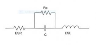
From the above picture of Equivalent capacitor parameters, it seems that if the ESR rises, the charge time would increase, yielding a falsely high capacitance by the C = T / R method.
The leakage resistance seems fairly straight forward to test, but (Hi Indianajo) what do you mean by wattage test? Is this the amplifier output power? Is there a simple way to measure the actual charge stored by the cap? Would this be Joules (energy) rather than power?
Here's something further;
"The discharge time can also be calculated. In this case, the time take by the capacitor to discharge to 36.8% of the peak voltage can be measured."
This article did not elabourate, but---and I'm really going off on a tangent here---Could the 'capacitance' value determined by charging AND a value determined by discharging, be somehow compared to determine the effect of ESR?
Thanks all, for your help, and tolerance!
Hi Kay;
Removing the 40+ year-old sockets would eliminate the loose connection issue, but, stubborn as I am, I am hoping that a gentle squeeze on all 48 connection points will restore these sockets. The output devices seem to have been changed a number of times and I believe the rough handling may have distorted the sockets.
- Home
- Live Sound
- PA Systems
- Peavey CS800 Doorstop to Decent