I help a friend out when his speakers give up on him, and I've done a few studio monitor amplifier replacements in the past, but recently he gave me a JBL EON 15P1 which wasn't working.
When testing, I suspected the amplifier was gone. It's a bi-amp setup, so the strange bit was that the tweeter was also dead. When looking closer, I found that the LF (4 ohm) and HF were working perfectly, and the input circuit was also looking good. The amplifier board must have been to blame. It also looked like a previous repair was done, and the new power transistors were SanKen 2SA1386 and 2SC3519 (far too small, in my opinion). Power supply measures at +-40V.
I have small amplifiers for about 50W and I adapted my design for 180W. This would require me to build an extra power supply for the 50W, and build and test a whole other amplifier. I decided to build the 180W, build a little power supply for the input board, and put in a basic crossover. Something like this:
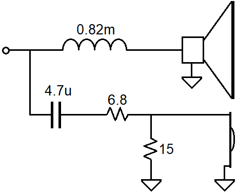
The end result seemed to work pretty well, thankfully. The speaker isn't used for high fidelity anything, it's probably for voice and perhaps as a stage monitor in a small informal setup. The speaker was pretty well used, if you know what I mean.
Was this a good idea? Any thoughts on such a modification?
I was looking at the schematics for this speaker, and it's an interesting design. I must commend JBL for an incredible speaker design! It didn't look like they cut any corners, like I've seen so often before from big-brand companies. The circuit was built with good components, had excellent construction, regarding the application, and the aluminum chassis was a clever design. The woofer is part of the speaker chassis, as is the tweeter horn. Very nice indeed.
What I mean by interesting design was the supply voltages for the power stage and the amplification stages of the amplifier. It seems a little overkill for such a simple power supply. I mean, surely a simpler design with a slightly simpler power supply would suffice? I think they were maybe going for 130W in the LF amp and 40W in the HF amp, so perhaps the design was to limit the LF power? Have I gone too far with a 180W capable amplifier?
When testing, I suspected the amplifier was gone. It's a bi-amp setup, so the strange bit was that the tweeter was also dead. When looking closer, I found that the LF (4 ohm) and HF were working perfectly, and the input circuit was also looking good. The amplifier board must have been to blame. It also looked like a previous repair was done, and the new power transistors were SanKen 2SA1386 and 2SC3519 (far too small, in my opinion). Power supply measures at +-40V.
I have small amplifiers for about 50W and I adapted my design for 180W. This would require me to build an extra power supply for the 50W, and build and test a whole other amplifier. I decided to build the 180W, build a little power supply for the input board, and put in a basic crossover. Something like this:
The end result seemed to work pretty well, thankfully. The speaker isn't used for high fidelity anything, it's probably for voice and perhaps as a stage monitor in a small informal setup. The speaker was pretty well used, if you know what I mean.
Was this a good idea? Any thoughts on such a modification?
I was looking at the schematics for this speaker, and it's an interesting design. I must commend JBL for an incredible speaker design! It didn't look like they cut any corners, like I've seen so often before from big-brand companies. The circuit was built with good components, had excellent construction, regarding the application, and the aluminum chassis was a clever design. The woofer is part of the speaker chassis, as is the tweeter horn. Very nice indeed.
What I mean by interesting design was the supply voltages for the power stage and the amplification stages of the amplifier. It seems a little overkill for such a simple power supply. I mean, surely a simpler design with a slightly simpler power supply would suffice? I think they were maybe going for 130W in the LF amp and 40W in the HF amp, so perhaps the design was to limit the LF power? Have I gone too far with a 180W capable amplifier?
I would repair the amplifier. It is a standard discrete devices schematic and not complicated at all. LM3886 HF amp and discrete LF amp. If neither work, it is the power supply at fault. Even simpler.
Ok, thanks. Sounds like a plan for next time. The power supply seemed fine though; that was the puzzling bit.
The chip is LM3876, but either way, it's a mission to desolder those. I also don't have access to many of the transistors called for in the schematic.
I didn't have time to diagnose much more than what I did, and I planned on having a look after giving the speaker back so that I could see what was wrong, but he took the amp board too. It did have a previous repair and the output transistors weren't proper. Also, I have a lot of experience with trying to get those exact transistors here, and they've all been fake, so I wonder if that may have been the case. Still doesn't explain why the HF wasn't working at all. My guess is that the output was blown, triggering the overload protection, muting the HF as well.
The HF is muted when there is an imbalance on its output and is not affected by the LF amp state.
They don't normally fail together, the LF may fail but the HF will continue.
I expect it is a bad connection on the main amp board causing total failure.
I would have loved to do some testing, but I don't have the board anymore.
Sorry but that is a 2 (two) ohm woofer, actual Voice Coil DCR is around 1.4 ohm or so.
That´s why rails are so low, "just" 50V, yet amplifier is *powerful* .
Your power amplifier, if not *specifically* built for such a low impedance load, may seem to play loud and clean ... and then overheat and die.
Please recheck that.
That´s why rails are so low, "just" 50V, yet amplifier is *powerful* .
Your power amplifier, if not *specifically* built for such a low impedance load, may seem to play loud and clean ... and then overheat and die.
Please recheck that.
Sorry but that is a 2 (two) ohm woofer, actual Voice Coil DCR is around 1.4 ohm or so.
That´s why rails are so low, "just" 50V, yet amplifier is *powerful* .
Your power amplifier, if not *specifically* built for such a low impedance load, may seem to play loud and clean ... and then overheat and die.
Please recheck that.
Thanks. That makes sense. I did measure it, and the DC measurement was about 2.6 or 2.8 ohms. I designed the amplifier to handle the abuse, and also to limit the output current somewhat. I assumed it was 4 ohms because of the JBL material I've read. I saw specifications for a 4 ohm version and an 8 ohm version, and therefore assumed the former based on the DC measurement. I did, however, design for 3 ohms, assuming it would have a minimum of 3 ohms, and the series inductor has about 0.5 ohms DCR.
The original design uses a 2SC3281 and a 2SA1302 for the output. The amplifier I worked on (what looked like previous repair) used 2SA1386 and 2SC3519, which can't have a hope of lasting. I more than doubled that capability and the final result has much better SOA than the original spec transistors. I designed the output to operate well below DC SOA derated for 50 degrees case temperature for a 3 ohm load.
With a 3 ohm woofer, the original amplifier would be about 230W, which is too much for the specified transistors. The original spec says it is 130W. This was confusing to me, but I haven't looked at it much more due to lack of time.
jbl -gtr 1001 momoblock
i reacently purchased this amp had it playing for a couple days one day i just started sounding real bad like it had a short .so i open the amp sure enough on the circuit board you can tell that something burne but you cant tell what it is because it desintigrated so my question is does anyone have any pic of one so i can se whats the part number
i reacently purchased this amp had it playing for a couple days one day i just started sounding real bad like it had a short .so i open the amp sure enough on the circuit board you can tell that something burne but you cant tell what it is because it desintigrated so my question is does anyone have any pic of one so i can se whats the part number
- Home
- Live Sound
- PA Systems
- JBL EON 15P1 Amplifier replacement