I'm considering the challenges of a 6 channel mini mic preamp/mixer to fit in a mint tin.
6 balanced phantom inputs, 6 pots, 6 mini toggle LCR mixer assigns, single stereo unbalanced output.
Not sure if there will be phantom switching, board space will be a problem.
Power supply will be wart or some sort of standard laptop supply. It could be dc or ac but I guess dc would be easier since there is one less step in regulation. Also considering a usb battery supply option but this will result ins less efficiency in the dc converter, more board space, etc.
A few basic questions to help me figure out if this would be doable:
-Does a a trimpot or mini pot exist that has similar rotational life to a regular pot?
Fitting 6 pots and 6 mini toggles into a small space is one of the challenges.
-For the power supply filtering and regulation, let's say I have a 12-20v dc source, about how much board space and height would be the minimum needed for 48V, V+, V-? I think the capacitor height and regulator dimensions are the limiting factor here, so I'm wondering about fitting two boards into the case as the maximum combined height is .83".
-I am thinking of using soic that1512's and running them all full gain to take advantage of noise performance and then attenuating at the output. Any problems with this? Also I think these have phantom protection diodes built in so it's less board space. Any other instrument amps that would be better for the application?
-The mixer section might be able to be all passive if I only lose 6db gain in summing, correct? Or will it still need to be active to properly drive the output into a portable digital recorder?
-Re: wire to board, is it ok to wire mini jacks directly to through hole pads on the board as opposed to some sort of molex connector. This will save a lot of space.
Anything else that will make this undoable? I don't want to waste time planning any more if it can't be done reasonably well.
Caution: Behringer shill ahead!
Not really DIY (or a mic mixer) but I have been happy with the Behringer MX882 line level mixer. I needed 4 channels for a "preamp" unbalanced, balanced ins/outs. This fits the bill. Also needed a lot of gain so some channels I use an extra +15 dB of gain from a 2nd channel. A lot of people here dislike Behringer. I have been a happy user of their amps and now this "preamp" ($99) and it's very hard to beat price-wise. Cheap, reliable mass produced items can take the fun out of DIY
Not really DIY (or a mic mixer) but I have been happy with the Behringer MX882 line level mixer. I needed 4 channels for a "preamp" unbalanced, balanced ins/outs. This fits the bill. Also needed a lot of gain so some channels I use an extra +15 dB of gain from a 2nd channel. A lot of people here dislike Behringer. I have been a happy user of their amps and now this "preamp" ($99) and it's very hard to beat price-wise. Cheap, reliable mass produced items can take the fun out of DIY
You might consider making one input also RIAA. It might be useful. It can be a mic input slightly modified. It can even be MC as that is close to microphone levels.The EQ could be on a push in card or DIL socket. You might even have subtle EQ for your mics on the cards. Perhaps 5 uS or whatever. Just a thought
A friend wanted to record 78's. He asked me what specailist phono stage to buy. I said use his mic preamp and do EQ in the digital domain. He is very happy with this. Denon 78 into 600 R is fine. As he wants it digital why not.
A friend wanted to record 78's. He asked me what specailist phono stage to buy. I said use his mic preamp and do EQ in the digital domain. He is very happy with this. Denon 78 into 600 R is fine. As he wants it digital why not.
I looked at the alps rk097, six of these will just fit across the width on the front. Is there a smaller good quality reverse log pot, particularly in height? If it's low enough I can just keep it enclosed and not have to drill front holes.
Also looked into the digital controlled 1571. What would be the smallest and easiest serial controller? Is there some sort of off the shelf linux/android application?
I think I can eliminate panning by having 3 dedicated left and 3 dedicated right channels on the input.
So far things looks doable, but I have not yet looked enough into the power supply/regulation and if there is enough board space.
Can someone provide a very simplistic explanation of what would be needed in a bare bones SPI controller, interface, power for the THAT1571. I'm trying to determine if this will be somehow smaller/easier than 6 pots.
As far as I can tell I would need an display, buttons, 5v power supply, control logic board, and code for the controller.
As far as I can tell I would need an display, buttons, 5v power supply, control logic board, and code for the controller.
For control you could use Arduino its not really hard to write code for it.
As for front panel you could maybe get one of those small 1.3" oled displays. Add few small momentary switches and one rotary encoder. Rotary encoder with combination of push buttons can be used to set level for any or all of the ICs.
After quick look at the 1571 datasheet you will need another opamp after 1571. They suggest their own 1570.
Also THAT 1571 is 32pin QFN package which is not really diy friendly unless you have soldering oven.
Thank you Zoid for the information.
I had sort of given up on this project until recently. By chance I came upon a spare neumann part that is an all in one phantom power supply and regulator n a 15x56mm package. I got the idea to use this for phantom voltage and then create 6 preamp sub-boards of the same size perpendicular to the main 56x96mm board, saving roughly half the space and freeing room for the preamp regulation supply and mixer section.
So I guess the 1571 is out due to the qfn package, but small pots are just as good for my purposes anyway. I can just about squeeze 6 rk097 pots along the front of a tin. IF there are smaller pots anyone knows about I would like to know. I was also toying with the idea of socketing some trimpots, because trimmers are smaller, and sockets so when they wear out they're easy to replace.
Not sure if it's a good idea to take my regulated 48V and regulate it down to 15 and then invert that for my -15v. I guess if I use a wallwart then this should be fine since I won't be worried about draining a battery.
For space savings I was thinking of dedicating 3 left channels and 3 right channels but I'm not sure how I can send one input to both left and right with the minimum amount of space on the case. Maybe a solution is dedicated 2 left, 2 right, and 2 center.
Also unsure of how to mute unused unused inputs so they don't add any noise.
Back on the ball with this project.
Design currently:
spi gain controller either arduino or diablo16
3.2“ screen
6 mini that 1580/5171 mic pre cards, 3.5mm input, phantom on/off mini slider switch
48v,+-15v,3.3v switching supplies (no other choice for small space)
dedicated channel/pan: 1L 2R 3L 4R 5C 6C
Last step is to figure out summing. So far I’m thinking passive shunt resistors
with center channels at higher resistance and then a 30db variable makeup gain via
two more 1580/5171 channels so the master out is roughly -15b to+15db.
Final output would be unbalanced after the summing.
Any help on the summing appreciated...
Last edited:
Ditched the digital gain control.
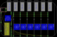
Current design is 6 channels of datasheet Ina217 preamps. Pan will remain fixed as above.
Picture attached of the motherboard layout which houses the channel, summing, and regulator cards. Space is tight.
Thinking out loud about the summing, after reading Forssell's article
(http://www.forsselltech.com/media/attachments/summing_buss.pdf)
It ocurred to me I don't really know exactly what I want the gain staging to be in the summing and following stage (recorder).
Leaning toward passive summing now, especially since summing channel inputs will be unbalanced.
Options are
- passive resistor network with no makeup gain. recorder can provide ~15db of line level gain.
-passive resistor network followed by fixed gain of ~15db.
-passive resistor network followed by variable gain of 0-15db or 0-30db
With passive summing all 6 channels need to be in the circuit. I do not understand how to handle channels with no inputs connected.
Power supply questions: Currently I'm using LT8570 for phantom but was instructed to bump up its output a bit an then use a linear regulator also.
For bipolar +-15 as of now there is an Xp power Itx1215S block, just out of laziness and keeping parts count low. Probably this too should have linear regulation as well. I could use ldo's and bump it down to 14.x. Other possibility is LTC3265 followed by linear regulators.
http://www.ti.com.cn/cn/lit/ds/symlink/ina217.pdf
page 13, what is the current draw of the opa137 shown, is it just quiescent current in the datasheet?
I guess this will push total current consumption too high for the LTC3265.
Attachments
Last edited:
Why not using active summing? It takes just one audio OP-Amp.
With active summing you can achieve 0dB gain loss, for each channel, and you can disconnect unused channels without affecting the gain of the active channels at all.
Furthermore, you could easily implement a master volume potentiometer in the feedback path of the OPA.
With active summing you can achieve 0dB gain loss, for each channel, and you can disconnect unused channels without affecting the gain of the active channels at all.
Furthermore, you could easily implement a master volume potentiometer in the feedback path of the OPA.
I'm reading the section on active summing now from the Forssell article, still unclear on some concepts. ACN is more complex than passive. I anticipate difficulty with the grounding scheme when I get around to it, and adding more difficulty on top of that steered me to passive.
"The amplifier used in the ACN circuit must have its non-inverting input tied to ground. Any noise present on this ground will be amplified by the gain of the amplifier."
"If we can get the ground noise to be the same kind ofnoise present at each channel,
we can use this CMRR to help reject the overall noise. This is done by running a ground trace along with the summing buss signal trace and tying to each channel’s ground via a resistor"
"Another way to accomplish this type of noise reduction is to use a true balanced/differential summing buss.
A major drawback to this topology is that you need an additional amplifier in each channel to drive the differential buss, and any switching becomes more complex."
I guess I could go back to the that1580 which has balanced outs. Then 4 amplifiers are needed?
There's not a whole lot of room on the summing card. 57mm x 18mm
Still leaning toward passive since Forssell says for low channel count noise is probably not a big deal.
Last edited:
With active mixing, you just turn down the pots to the channels you are not using.With passive summing all 6 channels need to be in the circuit. I do not understand how to handle channels with no inputs connected.
Power supply questions: Currently I'm using LT8570 for phantom but was instructed to bump up its output a bit an then use a linear regulator also.
In the ultra small category, I'm using ST/MC33078 op amp for low noise, @ 2 ma/amp in a dual package. Sounds quite good. Couple of zeners with 2 resistors & 2 caps works for bipolar power supply off a wall-transformer. Currently I'm using a 18v race car wall transformer with 7.8v zeners for headroom for a 7 VAC FM radio earphone output. Other inputs are a CD player & dual RIAA magnetic phono inputs. If you need less headroom than 10 vpp you could use a 12 vac supply with +- 5.1v zeners for the analog ground.There is a toroid RF coil from a PCAT power supply on the DC in to keep the CB'ers and lamp dimmer hash out. RF bead on the DC wire in would be smaller. I'm too inexperienced to hyperventilate about low noise regulator IC"s for two op amps, and my zener PS sounds fine with 5 W zeners for the main rails. I've got 5 dual op amps, you may need smaller zeners. In the hiss dimension the RA88a is about the same as the tube PAS2 preamp - but has more hum.
For more compact 33079 is 4 amps to the package. 33078/9 is fast, need a local .1 uf + to - rail within a couple of inches of the package and a 33 pf around the feedback resistor, to not oscillate.
I don't know of any stereo trimpots. I do like the idea of socketing the volume pots for when they get dropout.
With 12 VAC supply you could use a couple of voltage doublers for the 48 vDC. Again a couple zeners could regulate. 1 transistor booster even better. The condensor mikes I'm using take 5.5 ma phantom power.
A mint tin is a bit tight but metal is important for RF screening & 1/4 phone plug inputs take some room. Fitting in the pocket is important for live recording at free events. I bend little boxes out of shim stock with 2 C clamps, a steel beam as anvil, a foot of flat 8mm steel for clamp, and two rubber hammers for the press brake. Use wood clamp around shim stock when drilling holes, to prevent the bit grabbing & bending the metal.
My 33078 circuit is in the RA88a 5 input mixer, which I bought for the box and the pots. It was noisy with 4558's and the internal power supply hummed from the transformer being next to the 50x gain op amp. RA88a will not fit in a pocket, but the circuit would with smaller pots. mcmelectronics sells a nice small dip project board for $1.70
Who needs behringer for something this simple? Cell phones are compact but the resulting recordings have **** fidelity. Its the mikes.
Best of luck with your progress.
Last edited:
Ramblings about p/s ideas.
I looked into some miniature module type dc-dc converters such as TI dcp02 series. At first it looked promising, but to get 100mA per +-15v and 48mA 48v they don't seem to make sense. For a stereo preamp without phantom they look very good though. TI rep mentioned startup/surge current of 750mA for these modules, I did not see this in the datasheets and that also may rule these out.
Another(likely bad) idea is putting a small dc module on each preamp card. There is just enough room for it, I might be able to squeeze in a regulator too, but then having a converter right next to the mic ins and having unregulated dc on the power bus is probably a terrible idea?
So it looks like the two options available are linear supply or stay with TI simple switcher module(s) into tps7a470/7a33 regulators for bipolar and lt8330>>LTC3012 for 48v. This is above my paygrade but for a tiny footprint I don't see any other choice.
The linear supply should be fairly straightforward, except I want to keep the box as small as possible and I do not want to do any metalwork. JLM ac/dc p/s board is perfect but I could probably get the footprint much smaller making my own boards. I considered buying an Aliexpress p/s just to use as a case since they are already drilled/cut and have ac inlets installed.
How hard would it be to gut an older style transformer wall wart and squeeze a 3 rail regulator in there? Maybe the transformer already in it would be useable?
Lots of progress. Mini ltc3265 bipolar power supply card now working, about the size of thumbnail. Preamp card is working, but I messed up the pot configuration.
I misread the info here The Secret Life of Pots
and used a 10k pot and 2k taper resistor, resulting in 1.666k total resistance. If that configuration can actually create reverse log from a linear taper then I need 50k pot and 12.5k taper resistor.
At the bottom of the page in that link, how is that reverse log? I hooked up my pot that way and resistance increases with clockwise rotation; I thought it was supposed to decrease.
Is it actually possible to create a reverse log rheostat from a linear pot?
I need a 9.5mm reverse log 10k pot, size of the bourns 3310 series. vishay p9 are 9.5 x 11.5mm, just a tiny bit too big.
 Thanks
I'm down to hopefully the last bits. Everything fired up and worked except there is some low level analog? noise on the master output. I was advised to try a battery supply to rule out the p/s as the noise source. Also it was unshielded when tested so maybe that was part of the problem.
The summing card uses an lme49720 which is notorious for oscillating or maybe also being sensitive to noise.
Hi weroflu,
Wow. What an amazing achievement. Gotta admit, as I read some of your struggles I sure didn't expect this beautiful thing to be knocked out this soon.
Couple things, though: 1) Still can't figure why you wanted reverse log taper pots, and 2) Sure hope no operator ever forgets to turn off P48 before mating/unmating the corresponding input connector. Momentary shorts are inescapable with TRS, and are pure hell on the circuits (XLR's don't have that problem, and connect Gnd first), at least those that don't have transformer isolation.
Anyway, huge congrats -- its gorgeous! Double wow.
Regards,
Rick
Reverse log pots are s.o.p. for these inamp mic pre circuits.
But the point is moot since I swiched over to digital gain control (That5171)
There is a phantom on/off microswitch on every channel, with a small 0603 blue led indicator.
To keep things this small 3.5mm connectors were a must, no way around it. Mini xlr's were even way too big for what I had in mind. It probably will not wind up being a commercial product so the operator will be me, or any adventurous people who want to spend too much money to have one built for themselves. I think I have already plugged channels in with phantom on with no averse results.
Im trying hard to motivate for the last push to finish it. Need to track down the last bit of low level noise. Hopefully within the next 2 months it will be done.
- Status
- This old topic is closed. If you want to reopen this topic, contact a moderator using the "Report Post" button.
- Home
- Live Sound
- PA Systems
- 6 channel mini mixer