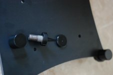
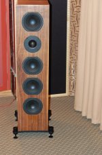
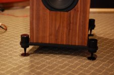
Thought these speakers needed some really good stands so I designed Base and spike system. Base is 1/2" laser cut plate steel. Spike is 3/4" 16 thread with 1/2" adjust.. 34pounds added to each side..
The speaker is much more solidly planted and the entire sound has improved...
If anyone would like these I can do more upon request but rather expensive...
The speaker is much more solidly planted and the entire sound has improved...
If anyone would like these I can do more upon request but rather expensive...
Attachments
As usual a work of art!Thought these speakers needed some really good stands so I designed Base and spike system. Base is 1/2" laser cut plate steel. Spike is 3/4" 16 thread with 1/2" adjust.. 34pounds added to each side..
The speaker is much more solidly planted and the entire sound has improved...
If anyone would like these I can do more upon request but rather expensive...
Nice work Joel, very smart.
Thanks!
This speaker is worth the effort
As usual a work of art!
Very nice words. Thank you!
Jdkjake, When we tuned the port on my set I had several length's on hand, 1/4 inch increments and used duct tape to seal the gap around the port. I ended up using the shortest one I had on hand and siliconed it in place The 30 ohm resistors really tighten up the bass. If you have been enjoying the way they sound I don't think I would change the damping material until you try different port lengths.
tpate,
What was the final port length (and internal diameter) you ended up using?
While I am able to tune the cabinets down in frequency as far as one could possibly want by increasing port length, I seem to have hit a wall with shortening the port to tune the cabinets up in frequency. Further, once the port length gets below ~75mm and recess in between the back panel stiffeners, the twin peaks start to get very uneven with respect to each other while providing no real increase in frequency. About the best I have been able to achieve is about ~1hz in measurable frequency increase.
I am struggling a bit determining the next steps in getting the port tuning up in frequency. Removing dampening material? Add mass inside the cabinet to decrease internal volume? Something else entirely?
Jdk, My final port length was 2.75 inches,I think. I will check to make sure tomorrow when I go to the studio. I used the expanded end of three inch pvc pipe which would be like a 3" coupling but doesn't have the rib in the middle of it. When Bolser and I were tuning the port we got all kinds of weird nodes until I put the duct tape around the port and sealed it good. I don't think lower than optimal tuning is as bad as higher. I will ping Bolser and see if he has any suggestions.
Thanks tpate. I am most interested in the final length you used. Our diameters are essentially the same as I used a coupler with the rib removed. During my experiments, just to be throrough, I actually took them all the way down to 25mm. 
The way I understand it, the port tuning can be in the 40's, near the free air resonance of the drivers for maximum output. They can be tuned low in the high 20's for maximum extension (at the expense of output) or in the mid 30's for the best extension/output compromise. This appears to be what Joe was aiming for with the tuning and has designed everything around that point.
spoonted brought up an excellent observation about the installation of my dampning material regarding the thickness and resulting density. The material I am using is advertised as 35mm deep. Since I am using a dual layer on the back, the thickness should be 70mm (give or take). Since the material is actually below the 50mm height of the back braces, I obviously compressed the material too much when I placed and glued it onto the back panel. Probably the same for the side panels. This most likely is making the material far too dense. Certainly, it is not installed and being used as designed. In any case, I should be able to "fluff" it up to the proper thickness. I will give this a try as well and report back.
Thanks tpate. I am most interested in the final length you used. Our diameters are essentially the same as I used a coupler with the rib removed. During my experiments, just to be throrough, I actually took them all the way down to 25mm.
The way I understand it, the port tuning can be in the 40's, near the free air resonance of the drivers for maximum output. They can be tuned low in the high 20's for maximum extension (at the expense of output) or in the mid 30's for the best extension/output compromise. This appears to be what Joe was aiming for with the tuning and has designed everything around that point.
spoonted brought up an excellent observation about the installation of my dampning material regarding the thickness and resulting density. The material I am using is advertised as 35mm deep. Since I am using a dual layer on the back, the thickness should be 70mm (give or take). Since the material is actually below the 50mm height of the back braces, I obviously compressed the material too much when I placed and glued it onto the back panel. Probably the same for the side panels. This most likely is making the material far too dense. Certainly, it is not installed and being used as designed. In any case, I should be able to "fluff" it up to the proper thickness. I will give this a try as well and report back.
I found that the material I used was also too dense. Replacing it with some experimental, much less dense material, made a huge difference to the LF output. I have since procured some material which I believe much more closely approximates the density of the wool/polyester material Joe Ras specified in his design. It is a 100% polyester product which is 75mm thick but can be peeled apart for the required thickness. It is made by "Rams Insulation" in Tullamarine Victoria for those who live in Aus. I haven't had a chance yet to pull them apart again to install it. I'll keep you posted on the results when I do. By the way I used the 90mm diameter port (storm water pipe) as specified by Joe. It's available at pretty much any hardware store in Australia. Not quite as pretty as a flared port though.
Happy listening.
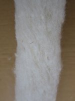
The material I am using is Monacor MDM-3. The material is a 75% wool, 25% polyester blend. When first unrolled, the material is condensed to a depth of ~20mm. A little manipulation is necessary to reach the full 35mm depth the material is designed to be used. At 35mm, the material is very light and airy.
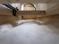
So, I pulled my back panel bats and "fluffed" them up to the 70mm depth possible by a double application of the material. As you can see, the rear panel is now significantly engulfed by the material. I also lightly fluffed the side material just a bit.
As expected, this had the effect of increasing the virtual volume of the enclosure, which, drove down the tuning point. So, while the material is being used correctly, I am still heading in the wrong direction.
Attachments

A new baseline, still many questions...
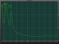
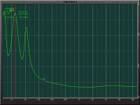
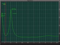
I decided I needed to understand the effect of damping material on the cabinet tuning. So, I broke down and removed ALL of the damping material from the cabinet. I left the port at the original length (~82mm). I then measured the impedance.
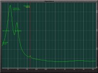
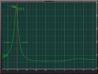
The results are pretty much the same as when I started this effort. The first two are the measurement with the port open. The third, with the port sealed. I cannot seem to get any significant tuning change (more than 2Hz or so) regardless of port length or cabinet damping.
As it stands now, it appears the overall volume of the cabinet is too large. That said, there are many things about this measurement I do not understand.
1) Can this measurement technique actually be used for this task? Joe implies this is the case in this post (http://www.diyaudio.com/forums/multi-way/97043-elsinore-project-thread-92.html#post2620798).
2) Why is the third peak present? I have checked and rechecked for leaks, most specifically forcibly sealing the tweeter opening and speakON jack opening to ensure they were not leaking any air. No change. Is this an artifact of the crossover itself? A non-issue? BTW, I am NOT referring to the blip at 158Hz, that is caused by standing waves in the undamped cabinet. I am referring to the peak at ~65Hz.
3) How can the cabinet volume be this far off? If anything, I am slightly short on the height (~5mm), but, the rest of the dimensions should be at least close if not dead-on to the design standard.
So, I am totally stymied at this point on how best to proceed. I can certainly fill and/or line the cabinet to reduce volume, but, is that the best way forward?
Has anyone else taken an impedance measurement of their Mark IV build? I would be curious to see if anyone else is having these types of results.
Comments are welcome and encouraged.
I decided I needed to understand the effect of damping material on the cabinet tuning. So, I broke down and removed ALL of the damping material from the cabinet. I left the port at the original length (~82mm). I then measured the impedance.
The results are pretty much the same as when I started this effort. The first two are the measurement with the port open. The third, with the port sealed. I cannot seem to get any significant tuning change (more than 2Hz or so) regardless of port length or cabinet damping.
As it stands now, it appears the overall volume of the cabinet is too large. That said, there are many things about this measurement I do not understand.
1) Can this measurement technique actually be used for this task? Joe implies this is the case in this post (http://www.diyaudio.com/forums/multi-way/97043-elsinore-project-thread-92.html#post2620798).
2) Why is the third peak present? I have checked and rechecked for leaks, most specifically forcibly sealing the tweeter opening and speakON jack opening to ensure they were not leaking any air. No change. Is this an artifact of the crossover itself? A non-issue? BTW, I am NOT referring to the blip at 158Hz, that is caused by standing waves in the undamped cabinet. I am referring to the peak at ~65Hz.
3) How can the cabinet volume be this far off? If anything, I am slightly short on the height (~5mm), but, the rest of the dimensions should be at least close if not dead-on to the design standard.
So, I am totally stymied at this point on how best to proceed. I can certainly fill and/or line the cabinet to reduce volume, but, is that the best way forward?
Has anyone else taken an impedance measurement of their Mark IV build? I would be curious to see if anyone else is having these types of results.
Comments are welcome and encouraged.
Attachments
Last edited:
@jdkjake,
Looks like you are measuring impedance with the crossover hooked up.
Can't recall exactly, but I believe the three peak behavior is related to the woofer impedance compensation network.
To see box tuning trends you need to hook straight up to the woofers, no crossover parts.
Looks like you are measuring impedance with the crossover hooked up.
Can't recall exactly, but I believe the three peak behavior is related to the woofer impedance compensation network.
To see box tuning trends you need to hook straight up to the woofers, no crossover parts.
@jdkjake,
Looks like you are measuring impedance with the crossover hooked up.
Can't recall exactly, but I believe the three peak behavior is related to the woofer impedance compensation network.
To see box tuning trends you need to hook straight up to the woofers, no crossover parts.
Thanks for the response bolserst. I did remove L4, R2 and C3 like Joe recommended, but, let the other crossover parts in the circuit. It appears the L4, R2 and C3 combo functions as the main impedance compensation for the lower woofers. That said, it is certainly easy to bypass the crossover altogether. I will give that a shot.
I am also reviewing all of my wiring just to be sure it was not something obvious. So far, everything looks correct. We shall see what things look like with the crossover out of the circuit.
Mystery Solved!!!
I found a wiring error in one of my speakON harnesses. Turns out it was the one I was using to make all the measurements (DOH!!). Turns out that harness did not return negative from the lower drivers. As such, the lower drivers on the device under test were essentially out of the circuit. Not sure how that happened as I thought I had verified the wiring harness properly both in and out of the cabinet. Nevertheless, a mistake was found and corrected. I also TRIPLE rechecked everything. I am satisfied all is wired as it should be.
Lo and behold, with L2, R4 and C3 out of the circuit, the impedance measurement completes as expected. YEA!!
So, using the original port length as well as the cabinet that I did not mess with in terms of damping material, the port tuning is coming in right around 36Hz. Now I need to restore/fluff the damping material properly, measure again and then adjust the port lengths properly.
What an experience!! Man did I learn a lot tracking that down!! It's all good!
Oh yeah, they do sound much better with all the drivers functioning properly on BOTH speakers.
I found a wiring error in one of my speakON harnesses. Turns out it was the one I was using to make all the measurements (DOH!!). Turns out that harness did not return negative from the lower drivers.
As such, the lower drivers on the device under test were essentially out of the circuit. Not sure how that happened as I thought I had verified the wiring harness properly both in and out of the cabinet. Nevertheless, a mistake was found and corrected. I also TRIPLE rechecked everything. I am satisfied all is wired as it should be.Lo and behold, with L2, R4 and C3 out of the circuit, the impedance measurement completes as expected. YEA!!
So, using the original port length as well as the cabinet that I did not mess with in terms of damping material, the port tuning is coming in right around 36Hz. Now I need to restore/fluff the damping material properly, measure again and then adjust the port lengths properly.
What an experience!! Man did I learn a lot tracking that down!! It's all good!
Oh yeah, they do sound much better with all the drivers functioning properly on BOTH speakers.
Attachments
I found a wiring error in one of my speakON harnesses. Turns out it was the one I was using to make all the measurements (DOH!!). Turns out that harness did not return negative from the lower drivers.
Aaah, OK. The lower drivers would be acting like passive radiators, loading the upper woofers.
That explains the dip in the impedance curve shown in the 3rd pic from your posting #1251.
Congrats on tracking down the wiring error.

Whats that program you are using for the impedance charts.
I have been using an iPad app from Studio Six Digital called AudioTools. I am coupling that with their iAudioInterface2 device. A really nice, compact and portable combination. I really like it. You have to rig and calibrate a custom cable to take the impedance measures, but, it is really simple and straightforward. Makes short work of impedance measurement, that much is for sure.
Do be aware, Some folks don't care for the ala carte nature of audioTools as purchasing a lot of the modules can add up quickly. Personally, I like buying only the units I need as I need them.
I also popped for a CM-125 calibrated mic kit. I have yet to use that extensively though. As I get better with it, I will publish some in-room acoustic measurements as well. Good stuff.
After reading your post JK I disconnected my lower two LF drivers just to hear the difference. It makes the sound quite thin and forward. Interesting. I must admit that when I first fired mine up I had them out of phase. I only had about twenty minutes to listen to them before heading out (to my physio) probably as a result of lifting them. I thought they sounded a bit off but it was only whilst playing Dark Side of the Moon (yes I am a 70's rock tragic) a bit later, which has a bit on the second side with deliberately recorded out of phase laughter that the penny dropped as the laughter was heard planted right in the centre instead of the intended ethereal surround effect. I guess I was in too much of a hurry to fire them up. Live and learn.
Happy listening.
Happy listening.
I have been using an iPad app from Studio Six Digital called AudioTools. I am coupling that with their iAudioInterface2 device. A really nice, compact and portable combination. I really like it.
Thanks for the info,
I had a look at the website and its a neat bit of gear alright never even new it existed.
I wonder what results you,ll get for the port tunning using the mike and a low frequency sweep.
- Home
- Loudspeakers
- Multi-Way
- The "Elsinore Project" Thread