Something I have missed in all the threads. Differently sunk woofers compared to case, and also compared to differently sunk tweeter. Why sink the woofers more into the case in the first place? Shouldn´t they be aligned with the front ? and the tweeter (incl the wg) measured in phase/time for the correct position behind the woofers?
Woofers can be mounted to the face of the baffle or (sunk)recessed 4mm.. The waveguide should be flush.. I have a plan woofers not recessed and waveguide forward 4mm..
The tweeter gaping is not a design parameter.. I'd like to measure the effect one day..
To busy lately.. I miss the Elsinore

Woofers can be mounted to the face of the baffle or (sunk)recessed 4mm.. The waveguide should be flush.. I have a plan woofers not recessed and waveguide forward 4mm..
Correct. If this was a Butterworth time-aligned filter, this would have been more critical, but the Renegade Tweeter Theory tells us that the trailing pulse of the Tweeter matches positive with the leading edge of the Midrange producer. So making the relative offset shallower just means that the optimum focus point it a little further away from the front baffle.
It changes from about 1.6M and that is OK, it may well be a benefit to have it a little further away. Since Butterworth can only max at 50% summation and the Elsinores can max at 100%, then an acceptable "window" of 90-100% is still hugely better than Butterworth time alignment. Also explains why Elsinores have a much wider window and hence much better power response. Relatively speaking, the Elsinores are fairly forgiving when it comes to time alignment.
Cheers, Joe R.
So making the relative offset shallower just means that the optimum focus point it a little further away from the front baffle.
It changes from about 1.6M and that is OK, it may well be a benefit to have it a little further away. .
Sound promising.
Looking at the dawings of WG a recessed WG with the TW directly towards it will recess the TW 15 mm in total. That will put the TW 15 or 19 mm behind the WF recessed or not recessed . Both within the range, but not recessed would create a wider sweet spot closer to the speakers, right?
With a 1,5 mm gap the distance would be 16,5 and 20,5, right?
Hälsningar/H
I really dont know how many times i have read through this thread now looking for things. My wife probably know :-(
This time looking for the principles for the cabinet stiffening. The two long pieces in the back confuses me. Why two of them going from top to bottom instead of number of them from left to right lets say every 200 mm of the speaker height. This would according to my very small knowledge of mecanics create a stiffer back panel of the speaker. Is it about airflow inside?
Couldnt find the answer in the thread or in the rasmussen home page.
I really dont know how many times i have read through this thread now looking for things. My wife probably know :-(
T
You got it bad. LOL
Oh dear, here we go, so I am going to type this out quickly and let the brain just click into gear... I have to get to work.
Re cabinet stiffening, yes it is in there somewhere because I do remember making comments about the general method. It uses something that can be called "asymmetrical longitudinal" bracing. Bracing across, from side to side, might seem a good idea - it may make the box "stronger" but not that is not necessarily what we want to do. It's about vibration control.
Many years ago, Cooke and Fincham from KEF would publicly demonstrate bracing of panels.
1. Take a rectangular panel - give it the old knuckle test and see how "lively" it sounds.
2. Now put bracing around all four edges of the panel, simulating the panel being part of a box, use knuckle test - and it makes hardly any difference at all. So bracing the edges is useless. A panel as part of a box is not well braced via its corners of the box
4. Now put a brace across the short dimension of the rectangular panel - this will simulate your idea of cross bracing - I can tell you, hardly any more successful than edge bracing.
5. Now put the brace down the centre of the panel length wise - this is now "longitudinal" bracing. Finally we have some success, it is noticeably better damped. But we are not finished...
6. Now still use the same brace, but NOT down the middle, but OFF-centre. Now we have "longitudinal" and "asymmetrical" bracing - and far more successful - the knuckle test sound significantly deader, there is less ringing.
This is what the Elsinores does - note the asymmetry where it braces the Side Panels. Not so easy to do on the Rear Panel, but it has TWO braces, and while symmetrical to each other, they are individually asymmetrical to the Rear Panel as a whole.
Of course there are other issues, as you mention, such as air-flow. One problem in tall cabinets is a vertical "pipe" resonance. But the Elsinore through four drivers along the length of the "pipe" means there is no vertical resonance - this can be confirmed by the impedance plot.
It is rarely mentioned, but any really bad cabinet resonances always shows up in the impedance plot. Go online and check impedance measurements of various speakers, especially if they are slim and floor standing and have a pipe resonance, it will be there for sure. The same will apply for cabinet resonances.
If you have a signal generator - or a sweep CD - and a Doctor's stethoscope, sweep in the area between 100 Hertz and 1 KHz while listening to the panels via the stethoscope. You can clearly hear cabinet resonances at certain frequencies and how bad they are. Even the most expensive cabinets will have some, but better controlled.
But the Front Panel needs to be the best controlled off all - it is weakened by the holes for the drivers etc - and any movement there will of course affect the "focus" - a bit like camera blur in reverse. Here bracing is particular troublesome - so what the Elsinore does is make the Front Panel TWO pieces and the cut-outs for drivers via those two panels allow us to 'sculpt' the Front Panel as a whole. Make it extremely strong and "avoid" it to act as a "panel" in the first place. Also, add extra mass where the Tweeter is mounted as there is where you want least movement. A block cannot resonate like a panel even if it has the same mass.
So, bottom line, here we are trying to prevent panel resonances by preventing the Front Panel to "act" as a panel as much as possible in the first place.
Side Panels and Rear Panels are slightly less important, but maybe also dangerous to say that. Good technique needs to be used. The problem is that most materials ring, and MDF certainly does. That is why if somebody asks me about alternatives to MDF, I certainly am in favour off that - and using the same technique works for those alternative materials as well. But MDF is still usable and the Elsinores work well, not because of MDF, but in spite of MDF. Mine are MDF, because when people come here, that is what they should hear - and it works. Not perfect, but it works.
Now I will get off my soap box.

Back to work.
Cheers, Joe
Joe, I didn't know about the KEF experiments (though not surprised) but I do remember reading that Jensen (when they were a speaker company selling their big coaxial and triaxials and not just a trade name) recommended vertical bracing of a panel as opposed to horizontal bracing. If I recall correctly, they suggested it raised the resonance whereas the horizontal didn't (and those were big boxes with big panels). The idea of asymmetrical bracing is logical as it would produce two different resonant points as opposed to 'doubling' one.
Joe, I didn't know about the KEF experiments (though not surprised) but I do remember reading that Jensen...
Well, I didn't know about Jensen, so good one!
Yes, the basics of it is quite simple - but not always immediately intuitive.
Remember the B&W "Matrix" Box idea? That was an interesting approach as well.
Cheers, Joe
" Also, add extra mass where the Tweeter is mounted as there is where you want least movement. A block cannot resonate like a panel even if it has the same mass."
Can anyone explain why the tweeter needs the exta attention regards resonance campared to the woofer?
It seriously affects the imaging - and that is not an area that I want to be compromised.
In short: Because the wavelengths are so much shorter. Speed of sound is 340 Metres, divide by the frequency = wavelength.
At 20 Hertz it is massive 17 Metres
At 3KHz Crossover point is a tiny 11mm.
Even 0.1mm movement would be catastrophic as that is only about -40dB down. Not too mention a potential rattle, but by that time the sound would have gone off.
Think of it as camera blur in reverse. If the camera moves the picture is blurry. But if the subject also moves, that too causes blurring. But in this case, the shorter the wavelength, the worse the problem. Hence the strongest part of the box needs to be where the Tweeter is mounted.
Cheers, Joe
I just decided to build Elsinore. I'm from Asia. is there anywhere I can purchase 830875 and tweets in Asian? what about Europe? in Germany?
any help is much appreciated

You got it bad. LOL
...........
Now I will get off my soap box.
Back to work.
Cheers, Joe
Sorry about hindering You from getting to work
I knew it wasn´t a coinsident but I just couldn´t find it in the htread or on your web site. I should have known better to ever think of something in this project not thought about or based on some theory and measurment. Never again - promise!
Out project are slowly taking it´s format.
We are about to build the cabinets with recessed mid/woofers wich makes the cabinet volume smaller. But to reinforce the baffel/front panel even more we will use 25 mm material instead of the 18mm. That will increase the volume (elements moving forward), but to reinforce the baffel/front panel even even more we will use a 2mm damp mat at the back of it. Back to "normal" exactly. Will produce new drawings.for someone interested to use.
Will also not use terminals for the cables out through the back panel as it weakens it (and is a unnecessary cost & contact point). Will go straght out with the four twinned (Look here - amazing result Svalander Audio AB - Flätarskola för ljudintresserade ) cables into an outide "Crossover box", filters according to the latest drawing, bottom plate with feet, epoxy WG etc.....
Once again - tnx Joe, Joel ..... for everything!
But to reinforce the baffel/front panel even more
Anyone seen Maple core plywood?
Anyone seen Maple core plywood?
Have used both plywood and solid wood earlier in different thickness (currently 60mm solid oak in Accutone set up) but i think we will go for 25mm MDF or a glued mix of 12mm MDF + 12mm Chip board (is that the right word?) - to get some mixed resonance. Wood in whole pieces are alive in my opinion..... but beautiful
Last edited:
I just decided to build Elsinore. I'm from Asia. is there anywhere I can purchase 830875 and tweets in Asian? what about Europe? in Germany?
I can ship them to you. I guess shipping would be fairly expensive, but I could get the woofers at a discounted price...
any help is much appreciated
We could ship them to you from anywhere in the EU but the shipping will be expensive. You will get them most shep in any US state without/with low VAT if you can´t find them in Asia (which sounds strange). Europe Audio would be a good place to look. We will probably order from them for at least 4 pairs of speakers in a short while. They give us (at least - working on more) 10% discount on the shopping cart prices for this level of order. I guess you could also look for using a company VAT number in Asia to get it from EU without VAT.
Go ahead - Just do it!
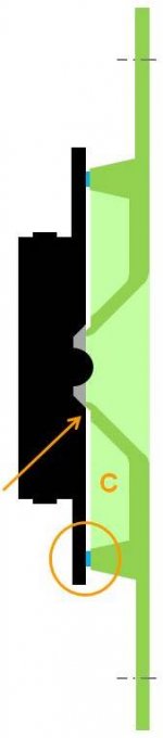
Working on the mold for the WG make me run into things. One about the gap some of the posts prefer. If, I say if, we design the WG in such a way that IF (but only then) the TW is mounted with a distance gasket (blue in picture - only shown as a square, but are going all around the beam directly towards the TW) there will be an opening gap (by the orange arrow) into a small "cabinet" (where the orange C is). This will make it possible to either fill the gap with another gasket OR don´t. If one don´t we have the possibility to play with the little "cabinet" and different fill within it (we are talking small). Anyone with similar experience?
Attachments
Last edited:
crossover question
might be somewhat off the current track, but i'm acquiring all the parts for this to start in a couple months. quick question: what exactly does L4 R2 C3 do? is it to quell a resonance at about 60hz? i'm trying wrap my head around that huge coil
thanks,
Scott
might be somewhat off the current track, but i'm acquiring all the parts for this to start in a couple months. quick question: what exactly does L4 R2 C3 do? is it to quell a resonance at about 60hz? i'm trying wrap my head around that huge coil
thanks,
Scott
Working on the mold for the WG make me run into things. One about the gap some of the posts prefer. If, I say if, we design the WG in such a way that IF (but only then) the TW is mounted with a distance gasket (blue in picture - only shown as a square, but are going all around the beam directly towards the TW) there will be an opening gap (by the orange arrow) into a small "cabinet" (where the orange C is). This will make it possible to either fill the gap with another gasket OR don´t. If one don´t we have the possibility to play with the little "cabinet" and different fill within it (we are talking small). Anyone with similar experience?
Cant say I follow completely but maybe your saying start with a mounting gap and then one can move it in to touch and out as if prefered..
- Home
- Loudspeakers
- Multi-Way
- The "Elsinore Project" Thread