Would it be possible to measure amplifier and driver distortion somewhat separately with the parallel resistor configuration to evaluate if amplifier (distortion) is affected by the load? At least magnitude of each distortion current could be estimated if nothing else.
Assuming driver generated current do not flow through the parallel resistor, then Sens 1 in attached image would contain amplifier generated current only and would indicate distortion generated by the amplifier. Sens 2 would show some of the amplifier current and all of the driver generated current. Replace the driver with another resistor to see what happened to amplifier distortion.
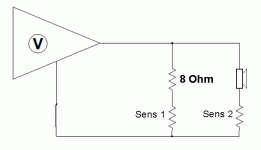
Also, swap in / out the parallel resistor while measuring acoustic distortion. If nothing happens distortion of amplifier is insignificant compared to distortion from loudspeaker driver? What if there was another resistor in series between the parallel resistor and driver, would amplifier distortion change or driver distortion? If both, whats the relative magnitude?
Assuming driver generated current do not flow through the parallel resistor, then Sens 1 in attached image would contain amplifier generated current only and would indicate distortion generated by the amplifier. Sens 2 would show some of the amplifier current and all of the driver generated current. Replace the driver with another resistor to see what happened to amplifier distortion.

Also, swap in / out the parallel resistor while measuring acoustic distortion. If nothing happens distortion of amplifier is insignificant compared to distortion from loudspeaker driver? What if there was another resistor in series between the parallel resistor and driver, would amplifier distortion change or driver distortion? If both, whats the relative magnitude?
Since (most) amps are voltage amplifiers, I think any distortion from the amp should be visible on the voltage, so just measuring the voltage on the amp output should reveal any distortion from the amp, just as in normal amp distortion measurements. While measuring amp distortion I have actually tried connecting a speaker as load, and in that case distortion (voltage) actually went down, but this will vary for sure, depending on the load the speaker puts on the amp. In general, lower impedance increases amp distortion. So, adding a resistor in parallel to the driver will most likely increase the amp distortion, and do nothing to lower driver distortion.
How many things are wrong with this picture? To many things to list, here are just a couple.Yes, the series resistor is an improvement. But how is this for a thought, if the speakers are 8 Ohm, then put an 8 Ohm resistor in parallel with the speaker, this presents a four Ohm load which should not be a problem for the amp.
The 8 Ohm resistor forces the amplifier to produce more constant current with frequency variation and flatten electrical current phase angle. I call it "poor man's current EQ."
View attachment 1088420
MANY OF YOU GUYS READING THIS SHOULD TRY IT AND LISTEN!
Also, it is important as a reference to show both voltage and current distortion. The voltage should show the ideal that we never get and the current distortion will also be greater.
What signal stimuli did you use? 1KHz is not quite enough, which I suspect you are using?
Did you use a current sense resistor? It should be low in value. Here is a suggested setup:
View attachment 1088421
An 8 Ohm driver usually has a DC resistance somewhere around 6 Ohm, so using a current sense resistor of 0.1R use s small very low distortion opamp like LM4562 or similar.
May I suggest that you try combine 150Hz and 1250 Hz, an example is shown below:
View attachment 1088423
Disclosure, this is Esa Merelainen's measurement.
First this can not be a SPL measurement, the measurement was taken across a resistor. It is a voltage measurement. SPL measurements are acoustic measurements taken with a calibrated microphone.
Second the measured voltage is amplified 60 times. This means that the noise floor is also amplified 60 times. 20 * Log60 means that the noise floor is raised 36dBr. Who knows what this measurement means?
Just giving it some thought today.
Current is a harsh redheaded mistress.
My personal preference is a brunette called voltage.
In the world of inductance voltage leads current. Voltage comes first.
Induced voltage or Back EMF is coil flux integrated over time filtered by the transfer function of the specific driver. You know things like hysteresis and varying Bl due to coil displacement
Joe keeping all the left and right thumb rules straight, Back EMF opposes the applied amplifier voltage and reduces current. Joe you ever sometimes speak of Back EMF as impedance.
Voltage is in charge. It is not nearly as simple as a fixed voltage output amplifier.
Thanks DT
Where do you think i comes from?F=i*Bl is what drives the mechanic-acoustic side. voltage is irrelevant here.
no, the voice coil is not a pure resistance. more correct version :F=U/R*BL is also true...
//
i=(U - EMF)/Re
where are is the DCR of the coil and EMF is the back emf induced in the coil EMF=dPhi/dt. this EMF can be highly nonlinear due to position dependent inductance and magnetic hysteresis. Current drive eliminates the influence of this term.
no, the voice coil is not a pure resistance. more correct version :
i=(U - EMF)/Re
where are is the DCR of the coil and EMF is the back emf induced in the coil EMF=dPhi/dt. this EMF can be highly nonlinear due to position dependent inductance and magnetic hysteresis. Current drive eliminates the influence of this term.
So, i = voltage / impedance. Looks a lot Ohms's law to me.
Volts do have a leading role.
Thanks DT
^^ TNT, absolutely should be measurable in acoustic domain, lets think about it for a second:
its current in the voice coil that makes the cone assembly move and we have sound. If there is no current there is no sound. Any (electrical domain) distortion mechanism has to make into current through the voice coil, otherwise there is no acoustic distortion because no current no movement no sound. Alright, some acoustic distortion is born in the mechanical parts but also that does not happen if the voice coil / cone does not move. And we absolutely have to make the voice coil move, to have the sound we want to listen to! Movement is what we want but byproducts of the movement, distortion current due to back-EMF voltage, is what needs to be reduced to reduce distortion in acoustic domain, right? Its distortion in acoustic domain that matters, current in the voice coil.
Electrical circuit composed of amplifier, driver, cabling and any passive crossover network has two sources in it. They are the amplifier on otherside of the circuit and the back-EMF in driver motor on the other side. How these turn into current is a question what the impedance is, for each. Amplifier originating current we want, driver originated current we want to reduce. Both flow through voice coil and make it move, only the latter is almost pure distortion isn't it, it was introduced in the system by non-linearities of the driver.
You could also have a hybrid system, low impedance output voltage amplifier with inductor in series makes low impedance for low frequencies and high impedance for high frequencies for the back-EMF as well. Back-EMF on low frequencies could make electrical damping mechanism for driver main resonance, which can be benefit as you suspect, but could also be replaced by acoustic or mechanical damping as Joe suggests. As frequency goes up the current is reduced by the inductor, also current that was generated in the driver! Example: we have low pass set by the inductor at 1kHz. If we command our amplifier to put out pure 1kHz in the circuit, with 0,001% distortion, the driver back-EMF adds 3rd order harmonic distortion voltage at 3kHz, but if this becomes audible is matter of the impedance, how much current the back-EMF volgate makes. The inductor increases impedance in the circuit, which is now much higher at 3kHz than at 1kHz. back-EMF voltage is always there, but it didn't transfer as much into acoustic domain due to higher impedance.
Read on Esa article here https://www.edn.com/loudspeaker-operation-the-superiority-of-current-drive-over-voltage-drive/
Last edited:
Joe mentioned 5:1 rule I think. edit. https://www.diyaudio.com/community/threads/the-elsinore-project-thread.97043/post-7098669So, in case of a constant voltage amplifier, in practice how much series resistance at least to put in place to have a current driven speaker unit? Say for midrange for example.
If you analyze the circuit from the driver side, driver as source, back-EMF voltage stays the same for any original sound you want to output with that particular driver because its property of the driver, so doubling up the impedance between driver terminals would cut current in half, I = U/R
edit.
thought experiment on the thumb rule: If 5:1 ratio between output and load impedance makes current drive, 40ohm output impedance of amplifier and 8ohm load would make one. Ok we don't have current drive amp but voltage amp with 0,1ohm output impedance. Lets examine what is the ratio in the circuit other way around, for the distortion generator, driver as source and amplifier as load. Now the output impedance is 8ohm and load is something like 0,1ohm (driver connected directly to voltage amplifier), thats ratio of 80:1, the driver works as current drive amplifier in the same circuit! All non-linearities in the driver turn into current and acoustic output. Reduce the ratio and less of it makes into current and acoustic distortion.
Basically the driver is amplifier as well, powered by the mechanical movement of cone and voice coil, which can be made move by amplified sound we want but also external forces like sound pressure from other drivers near by. Load impedance of this "distortion amplifier" determines if it has "current drive" or "voltage drive", same rules apply as with our real amplifier. Current we don't want from this amplifier, so better increase the load impedance.
Last edited:
JanRSmith, edit time over, and answer to your question was left out due to jargon.. 
It doesn't matter which name the amplifier has, acoustic distortion is reduced by reducing distortion current. Most distortion current originates from the driver, amplifier distortion is usually at least magnitude lower, THD 0,1% vs. 0,01% or better. Thus it makes sense to reduce distortion by driver. Read on Purifi articles and tech notes on their site for quick overview on the subject. And remember THD does not correlate with perceived sound quality, here the Purifi writings give some more ideas what is more audible and makes for better sound and its usually mid frequency problem. Woofer playgin low frequencies with quite some excursion makes distortion happen all of its bandwidth, even beyond low pass in active setup for example.
Its easy to evaluate what the distortion current originates from driver is by inspecting the circuit from drivers perspective, thinking driver as voltage source and what load impedance it has to get the current. Power amplifier is part of the circuit and as such part of the impedance. If its a voltage amp its almost a shortcircuit with its very low output impedance.
Last edited:
Hello All,
“Just For Fun”
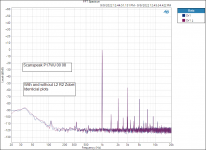
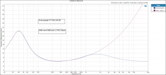
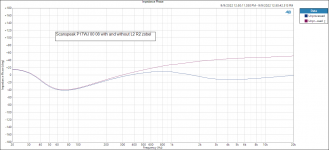
This morning I did some measurements on a Scanspeak P17WJ 00 08 driver with and without a L2 R2 coil model calculated 2 Resistor 2 Capacitor Zobel.
I used this driver and Zobel thinking that I have not observed any one with strong positive feelings about the model or driver on this thread. I am keeping the resistor and capacitor values under my hat so no one will call this a design or a competition.
The source amplifier is a Audio Precision APx 1701 with a sense resistor included.
There was no measured current distortion difference with or without the Zobel.
Note the reduction in impedance and impedance phase angle with the Zobel included.
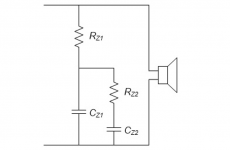
Thanks DT
The amplifier output voltage was 2 V RMS
“Just For Fun”
This morning I did some measurements on a Scanspeak P17WJ 00 08 driver with and without a L2 R2 coil model calculated 2 Resistor 2 Capacitor Zobel.
I used this driver and Zobel thinking that I have not observed any one with strong positive feelings about the model or driver on this thread. I am keeping the resistor and capacitor values under my hat so no one will call this a design or a competition.
The source amplifier is a Audio Precision APx 1701 with a sense resistor included.
There was no measured current distortion difference with or without the Zobel.
Note the reduction in impedance and impedance phase angle with the Zobel included.


Thanks DT
The amplifier output voltage was 2 V RMS
- Home
- Loudspeakers
- Multi-Way
- The "Elsinore Project" Thread
