A good paper about distortions https://acoustics.ippt.pan.pl/index.php/aa/article/view/1780/pdf_255 for someone who is new to current drive
Ah yes, Esa's more updated 2016 article, right at the beginning says:
"The latter [distortion] is because the driving force is determined by current, and the electromotive forces (EMF voltage components), that appear in series with the voice coil resistance, introduce nonlinearity in the relationship between the voice coil voltage and current."
That's the key right there. Distortion.
The only real point to using current drive is to reduce distortion.
But is it the only way?
THE difference I have with Esa is this, I want that low distortion to also work with so-called voltage drive.
Esa's position is that only current drive will give that lower distortion.
I disagree.
Hello Joe,
I am assuming that the tweeter plots in your post were made with a voltage source amplifier.
I also observe that both you and GedLee listen with your speakers toed in.
Me Too.
I also think of you as more artist than "textbook jockey".
Thanks DT
Re plots, correct. Voltage source is OK for amplitude/frequency response plots. But for distortion that is a different matter.
And I have found that it is actually best to ignore (but still look) what speakers do purely on axis. But for best performance, just a bit off-axis and design them that way.
Caption from the paper:
"Due to the simple inverse relationship between total load circuit impedance and the EMF-derived distortion, appreciable improvement is gained already at
intermediate source impedances. For example, when the source impedance equals the driver impedance (magnitude & phase), the reduction in the EMF derived distortion will be 6 dB compared with pure VC. Thus, CC is a feasible principle also for passive loudspeakers, where the crossover components compromise the source impedance of each driver, irrespective of whether VC or CC is pursued."
I think he acknowledges it as well as possibility to affect distortion with voltage drive, or Voltage Control amplifier in his words on the paper.
I need to read on this as its is interesting topic. I have active speaker system and adding some components between amplifier and driver in order to affect performance would be cool.
Does anybody understand what he, Esa, is saying?
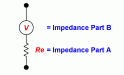
Esa's key words here are "total load circuit impedance and the EMF-derived distortion."
Here I will post this very simple but telling...:

The above, between the black dots, represents the "total load circuit impedance."
Where does the "the EMF-derived distortion" come from?
I can explain and so I shall attempt to explain it right now, so please read on...
The "total load circuit impedance" is Part A + Part B above. That determines the current drawn at any time from the amplifier.
If Part A is 6 Ohm and Part B is 3 Ohm and the source voltage is 9V, then the current will be 1 Amp and the heat dissipated in the voice coil will incidentally be 6 Watt. Part B is actually back-EMF of some sort, inductive back-EMF, motional-EMF and microphonic-EMF. All three presents themselves as less than stable impedances. When the change, the current of the amplifier changes, and that is "the EMF-derived distortion."
I also call it simply "current distortion" and nobody bothers measuring it and I hope to change that, or at least do my bit.
It is not Part A that causes "the EMF-derived distortion" as that is basically the Re DC resistance of the voice coil. For our purposes, it is almost a constant. Thermal change in Re is so slow as to only show up at very low LF (just ask Earl Geddes, he has made that very point.)
The key here is indeed "the EMF-derived distortion" and what causes it?
Impedance Part B is the cause!
What kind of impedance is Part B?
EMF!
Note the "V" in Part B?
Voltage!
That's right, EMF, or electromotive-force, is a Voltage!
All the imperfections of the driver make this Part B impedance unstable, which means that the Part A + Part B total impedance is unstable and draws unstable and corrupted current from the amplifier.
Esa also rightly says:
"For example, when the source impedance equals the driver impedance (magnitude & phase), the reduction in the EMF derived distortion will be 6 dB compared with pure VC..."
True! I am not arguing against Esa's logic. I agree with it.
It's just that it is not the complete story...
Some years ago I brought up certain matters with him and we agreed on the ratio of source/load impedance should be at least 5:1 - both Esa and I agreed on this.
Whether an amplifier is a current source or a voltage source is entirely defined by the amplifier's output impedance. We know this. Esa certainly does!
So if a speaker is 8 Ohm, then the source impedance of the amplifier and the 5:1 ratio tells us that it should be at least 40 Ohm.
For voltage source, it is the opposite that is true, apply 5:1 rule and for an 8 Ohm speaker, it should 1.6 Ohm or lower.
Esa sent me in confidence some suggested schematics that sacrificed speaker sensitivity and applied that 5:1 ratio. But it was not a practical solution.
But it did show he was thinking about it But so far he has not shown an example that works and gets you current-drive-like lower distortion from a voltage source.
I have!
I do believe that.
-----
So where does that get us?
Finding better ways to reduce EMF-derived distortion" while still using voltage sources.
And do it while we are using a voltage source. How?
1. The "EMF-derived distortion" mainly shows up as inductance above a few hundred Hertz. Make the driver better by reducing the internal inductance of the driver and then add the necessary external inductor. So if the driver inductance is 0.2mH and we add a 0.4mH inductor externally, then we have achieved the same reduction of -6dB that Esa uses his example. But the distortion is reduced further because by 10KHz the non-linear inductance can drop down to 30-50% compared to 1KHz. Now we have reduced distortion even further and -12dB on average.
A SINGLE INDUCTOR CAN GIVE YOU THE SAME ADVANTAGE AS CURRENT-DRIVE!
Can anybody here understand what I am saying? Be clever and you do not need a current-drive at all.
2. Make the driver have a constant and stable inductance. This is what Purifi does. The better the driver and the less "EMF-derived distortion."
3. Combine 1 & 2 above, and that is what the Purifi ULD plus Elsinores does.
4. The use of line sources can be used as well. Note the Elsinores have four series-parallel drivers below 500 Hertz and series drivers above that. A reduction in excursion is desirable to reduce "EMF-derived distortion."
4. Make the amplifier produce the same current at all frequencies. Now the induced "EMF-derived distortion" is suppressed. This is current EQ and also an advantage that current sources also do: The current phase angle will always be near zero degrees. Again, this is what Elsinores does.
And...
THE END GAME:
The Elsinores get you pseudo current-drive from a voltage source!
I am wondering how much of this is understood. I certainly understand Esa very well and I understand his argument, and I understand his aims.
But he is wrong to say that only current-drive can get us low "EMF-derived distortion."
So there you go...
Esa's key words here are "total load circuit impedance and the EMF-derived distortion."
Here I will post this very simple but telling...:
The above, between the black dots, represents the "total load circuit impedance."
Where does the "the EMF-derived distortion" come from?
I can explain and so I shall attempt to explain it right now, so please read on...
The "total load circuit impedance" is Part A + Part B above. That determines the current drawn at any time from the amplifier.
If Part A is 6 Ohm and Part B is 3 Ohm and the source voltage is 9V, then the current will be 1 Amp and the heat dissipated in the voice coil will incidentally be 6 Watt. Part B is actually back-EMF of some sort, inductive back-EMF, motional-EMF and microphonic-EMF. All three presents themselves as less than stable impedances. When the change, the current of the amplifier changes, and that is "the EMF-derived distortion."
I also call it simply "current distortion" and nobody bothers measuring it and I hope to change that, or at least do my bit.
It is not Part A that causes "the EMF-derived distortion" as that is basically the Re DC resistance of the voice coil. For our purposes, it is almost a constant. Thermal change in Re is so slow as to only show up at very low LF (just ask Earl Geddes, he has made that very point.)
The key here is indeed "the EMF-derived distortion" and what causes it?
Impedance Part B is the cause!
What kind of impedance is Part B?
EMF!
Note the "V" in Part B?
Voltage!
That's right, EMF, or electromotive-force, is a Voltage!
All the imperfections of the driver make this Part B impedance unstable, which means that the Part A + Part B total impedance is unstable and draws unstable and corrupted current from the amplifier.
Esa also rightly says:
"For example, when the source impedance equals the driver impedance (magnitude & phase), the reduction in the EMF derived distortion will be 6 dB compared with pure VC..."
True! I am not arguing against Esa's logic. I agree with it.
It's just that it is not the complete story...
Some years ago I brought up certain matters with him and we agreed on the ratio of source/load impedance should be at least 5:1 - both Esa and I agreed on this.
Whether an amplifier is a current source or a voltage source is entirely defined by the amplifier's output impedance. We know this. Esa certainly does!
So if a speaker is 8 Ohm, then the source impedance of the amplifier and the 5:1 ratio tells us that it should be at least 40 Ohm.
For voltage source, it is the opposite that is true, apply 5:1 rule and for an 8 Ohm speaker, it should 1.6 Ohm or lower.
Esa sent me in confidence some suggested schematics that sacrificed speaker sensitivity and applied that 5:1 ratio. But it was not a practical solution.
But it did show he was thinking about it But so far he has not shown an example that works and gets you current-drive-like lower distortion from a voltage source.
I have!
I do believe that.
-----
So where does that get us?
Finding better ways to reduce EMF-derived distortion" while still using voltage sources.
And do it while we are using a voltage source. How?
1. The "EMF-derived distortion" mainly shows up as inductance above a few hundred Hertz. Make the driver better by reducing the internal inductance of the driver and then add the necessary external inductor. So if the driver inductance is 0.2mH and we add a 0.4mH inductor externally, then we have achieved the same reduction of -6dB that Esa uses his example. But the distortion is reduced further because by 10KHz the non-linear inductance can drop down to 30-50% compared to 1KHz. Now we have reduced distortion even further and -12dB on average.
A SINGLE INDUCTOR CAN GIVE YOU THE SAME ADVANTAGE AS CURRENT-DRIVE!
Can anybody here understand what I am saying? Be clever and you do not need a current-drive at all.
2. Make the driver have a constant and stable inductance. This is what Purifi does. The better the driver and the less "EMF-derived distortion."
3. Combine 1 & 2 above, and that is what the Purifi ULD plus Elsinores does.
4. The use of line sources can be used as well. Note the Elsinores have four series-parallel drivers below 500 Hertz and series drivers above that. A reduction in excursion is desirable to reduce "EMF-derived distortion."
4. Make the amplifier produce the same current at all frequencies. Now the induced "EMF-derived distortion" is suppressed. This is current EQ and also an advantage that current sources also do: The current phase angle will always be near zero degrees. Again, this is what Elsinores does.
And...
THE END GAME:
The Elsinores get you pseudo current-drive from a voltage source!
I am wondering how much of this is understood. I certainly understand Esa very well and I understand his argument, and I understand his aims.
But he is wrong to say that only current-drive can get us low "EMF-derived distortion."
So there you go...
Attachments
I'm no expert on the field and understand it in high level simplified like so: varying impedance of driver, seen by the amplifier, makes distortion (in the system) and by reducing the variation reduces the distortion. Reducing variation in amplifier load impedance, which is mostly varying inductance of the driver, can be done by increasing total inductance with series inductor. Now total inductance varies less as big portion of it is outside the driver. Would this thinking be right?
But, what leaves me wondering if the thinking is legit, or what else is to it, because all this also (series inductor, or current drive) increases impedance seen by the driver so damping is less? Damping of driver "self movement", mechanical resonances or due to microphoned sound for example. Damping is made by magnetic field with the voice coil that resists change (this movement), which generated by current flowing due to back-EMF, voltage). If impedance seen by driver is higher then less current flows with given back-EMF voltage, which is less damping. Is this legit thinkin? In this case, with voltage control and series inductor we need good driver who doesn't need much damping for good sounding system, so we can "sacrifice" the damping, the low source impedance? in other words we sacrifice this damping, because its actually root of the distortion (allowing increased current)? what, brain twister?
Why current drive isn't popular? because of bad drivers with hard to equalize impedance? because of its harder to calculate bass boxes without damping from the amplifier?
sorry you might have written all this many times, bumped on the subject since few days and haven't read it all yet.
sorry you might have written all this many times, bumped on the subject since few days and haven't read it all yet.
Hi T
Oh boy, perhaps the first thing to correct here is this:
But, what leaves me wondering if the thinking is legit, or what else is to it, because all this also (series inductor, or current drive) increases impedance seen by the driver so damping is less? Damping of driver "self movement", mechanical resonances or due to microphoned sound for example. Damping is made by magnetic field with the voice coil that resists change (this movement), which generated by current flowing due to back-EMF, voltage)....
I am sorry, but this is not correct thinking. An increase in series impedance is a good thing.
Forget about damping here, this is a myth that has gone on for too long. It is the alignment that determines actual damping.
If impedance seen by driver is higher then less current flows with given back-EMF voltage, which is less damping. Is this legit thinkin? In this case, with voltage control and series inductor we need good driver who doesn't need much damping for good sounding system, so we can "sacrifice" the damping, the low source impedance? in other words we sacrifice this damping, because its actually root of the distortion (allowing increased current)? what, brain twister?
The back-EMF produces voltage, not current. The notion that current goes back to the ideal zero impedance and somehow becomes a brake, or damping, of some sort, the actual physics have never supported this idea. For one thing, even if such a current did exist, it would have to go through about 6 Ohm of DC resistance first before it sees the output impedance of the amplifier.
Also, the amplifier can only see a single impedance which is its own impedance plus the load impedance. The only time the amplifier can see its own impedance is when it is shorted to ground. Then the output impedance becomes effectively the load.
Think about that for a moment. Let us say the amplifier has a 1 Ohm output impedance. Let us say that the load is 8 Ohm. Now the claim would be that the damping factor is 8? What does that even mean? Not much. The amplifier now sees a single impedance and that is 9 Ohm.
Can you see the problem? The amplifier cannot see the split when it can only see the sum total. The amp might as well be 8 Ohm and the speaker be 1 Ohm. Or the split could be in the middle and 3.5 Ohm each. So the number 8 has no meaning at all. It's purely an artificial number. Why do so many people believe it?
There is a big misunderstanding between the bass alignment and what constitutes damping. The point is simple, and if you have heard the name Richard H. Small, then you know that I am quoting somebody who should know this:
The damping at LF is entirely defined by the alignment.
I know he said this, because he said it to me personally when I brought up the idea of damping factor of amplifiers and annoyingly told me the truth and would not discuss the nonsense any further. It took me a little while to realise he was right and I should have kept my mouth shut. Indeed the maths of Thiele-Small parameters tells that story entirely. I woke up when I studied them.
So added series impedance in the bass changes the alignment in the bass, the alignment changes, the damping changes. Above LF and when we get to frequencies where the inductance dominates (emotional back-EMF dominates at LF and inductive back-EMF as the frequency rises), and here additional series impedance will actually reduce distortion because it suppresses what Esa calls "the EMF-derived distortion" and read it in the context he uses and the subsequent words where he too says that added impedance is a good thing. Double it and he claims -6dB in distortion and points to odd-order products being suppressed.
Trust me, current sources do sound improved because the lower distortion. They may be problematic at LF and affect the bass alignment that reduce bass damping. But here it has nothing to do with a braking force being available due to current somehow reversing.
Incidentally, Earl Geddes says that a single driver cannot draw more current that the DC resistance of the driver. So any inductive impedance can only reduce current. The problem is that reduction not being stable produces "current distortion." This is the same as what Esa describes as "EMF-derived distortion"
I know that this is a difficult subject to understand. It takes mental effort. Thinking current is not easy, voltage is. But really... they talk about fake news and all that, but here is at least a damping folklore here that is not true.
cuThanks!
Pardon me writing again as I try to get understanding on this and I hope you could perhaps respond once more as we already got started a little bit.
Though of damping for my part was based on observation that if you take naked speaker driver on your lap, that is not connected to anything, and push the cone with your hand you can pretty much make the cone move but short its terminals you now need to push it harder as something resists the movement. I've reasoned this is because current can flow in the (short) circuit and magnetic field develops to resists the movement, damps it. This is due to voltage developing due to coil moving inside magnetic field, and shorting the terminals allows current to flow through relatively low (total) impedance and strong magnetic field develops as result resisting the movement. Isn't this basic thing, connect the bicycle magneto to the rim and you've got light but the dang magneto makes you do more work
I've expanded this idea in my imagination that similar thing happens as close to ~0ohm output impedance voltage control amplifier is connected between driver terminals, effectively a short circuit seen by the driver allows driver itself resists the movement, amplifier does nothing else than keeps the impedance low (I don't know how they do this). Thinking that the driver is source and amplifier is the load. So the amplifier is not responsible for damping the driver other than providing very low impedance between the terminals of the driver and driver damps itself.
At least this is the reasoning my primitive understanding of the stuff has let so far
Introduce more impedance in series on the circuit made by amplifier and driver and this damping effect reduces, the driver can now be pushed around by external forces and self resonance, and it does so more easily generating less current and thus weaker magnetic field to resisting the movement, less work. Voltage generated between the driver terminals by the external force moving the cone is the same regardless of impedance in the circuit but current is less as total impedance is higher. We could dampen the self resonance of a driver (box combination) or any other external forces moving the cone by mechanical damping(suspension?), or acoustic damping in the enclosure instead of relying this electronic damping by low source impedance.
All these thoughts kind of supports stuff I've seen so far, like there would be now huge peak in frequency response on a current driven woofer on its resonant frequency, where impedance is high, the resonance is not damped by the driver itself and we get the boost (due to extended period of ringing) so the idea here connected all the dots I've managed to grasp on the subject. Well, driver + box. We just need to make a box that makes the damping instead, in other words have desired frequency response.
Never thought this as just low frequency and bass box phenomenon though, we can use small drivers as microphones, current flowing there as well. Perhaps we could use voltage control for bass to have the damping and current control for smaller drivers that don't need it as bad?
I'd be glad if you could write some more on this, perhaps point where its going wrong. It would help better understand this, but I can study it from other sources as well.
Last edited:
Ah there is official terms for the stuff magnetic damping due to eddy current, which is due to low impedance between driver terminals with voltage generated by "back-EMF".
"Eddy current:
As discussed in "Motional EMF," motional EMF is induced when a conductor moves in a magnetic field or when a magnetic field moves relative to a conductor. If motional EMF can cause a current loop in the conductor, we refer to that current as an eddy current. Eddy currents can produce significant drag, called magnetic damping, on the motion involved."
From
http://kolibri.teacherinabox.org.au...ents-and-magnetic-damping-571-8079/index.html
magnetic damping due to eddy current, which is due to low impedance between driver terminals with voltage generated by "back-EMF"."Eddy current:
As discussed in "Motional EMF," motional EMF is induced when a conductor moves in a magnetic field or when a magnetic field moves relative to a conductor. If motional EMF can cause a current loop in the conductor, we refer to that current as an eddy current. Eddy currents can produce significant drag, called magnetic damping, on the motion involved."
From
http://kolibri.teacherinabox.org.au...ents-and-magnetic-damping-571-8079/index.html
Hi DT
I appreciate the effort. Thanks for re-reading.
I want to make a correction going back to #4782 where I made a mistake, I referred to FM distortion (Dopler) when it should have been AM (amplitude) distortion. I am scratching my head why I got that back-to-front. We are definitely talking about AM, amplitude modulated distortion. And this relates to physical excursions, which are of course amplitude.
Purifi drivers are stable in relationship to the load that they put on a voltage source amplifier, particularly when we have mixed LF with 1KHz for example.
My take: The Purifi ULP drivers produce less "current distortion" when the amplifier is a voltage source. So more explaining, so here goes...
Purifi has called referred to as "impedance modulation."
I then pointed out that impedance is related to current. So impedance modulations have to be current modulations. But what is being modulated?
The amplifier!
The current of the amplifier is being modulated. And that is not good.
That means the load that the speaker puts on the amplifier can induce current distortion and as a madman, I say YES!
This is what happens when the amplifier is a voltage source. But it does not when it is a current source. Then let us use a current source and all will be right? That is what some want you to believe, but the world is not getting converted to current-drive. Too impractical.
And maybe you don't have to anyway.
Just come up with different/better solutions that work with voltage sources.
I noted in a post here I note that Lars now called it "impedance/current modulation" and not just impedance modulations. Change impedance, and you change the current... of the amplifier.
The stock Elsinores already tackle FFM induced distortion by massively reducing LF excursions for a target SPL, sound pressure level. Then using the Purifi drivers, we can further improve and take the idea to the max. The Purifi drivers are even flatter FFM in the Elsinores for a target SPL, and they now have massive FFM headroom.
And that's the idea behind why I wanted to go for the Purifi rather than the suggested SB Sartori drivers. Were the guys willing to bear that cost and half a dozen put their hands up immediately and more to come.
Yes, you are right, this is IMD related, but have you read the Purifi blogs where LF (excursion, 40Hz from memory) and 1KHz mixed stimuli are used?
Please read the link below, it is about IMD/AM/FFM relationships, I think it will help put things in place.
Link: Low frequency harmonic distortion is almost inaudible. So what’s the point of low distortion drivers?
Yes, that is the crux of the matter, I will try to explain it as clearly as possible.
1. A voltage source can only control (regulate) the voltage, but in order to do that, it has to relinquish control over the current.
This is why the amplifier has to have a very low impedance and for the ideal voltage source that would be zero Ohm.
2. A current source can only control (regulate) the current, but in order to do that, it has to relinquish control over the voltage.
If point 1) is hard to understand, then 2) is perhaps even harder?
The ideal current source needs to have a very high impedance, and for the ideal current that would be infinity Ohm.
Do you see the whole juxtaposition? Things are totally opposites in a fascinating way.
Indeed all amplifiers can be modeled this way:
View attachment 1081407
Yes, all amplifiers can be modeled this way, as a voltage source followed by a series impedance.
The voltage source, it will be zero.
The current source, it will be infinity.
With tube amplifiers, it will have a value typically up to 5 Ohm, sometimes more.
Knowing the above, can we see where there is a mechanism by which a current source will have a 20dB (or significant) distortion advantage?
Yes we can. With a current source, the speaker load is not able to boss around the current like it can when a voltage source is connected to or speaker load.
Current sources produce less "current distortion."
The driver cannot boss around the current of the amplifier and hence lower current distortion.
Just as Purifi wants FFM to the forefront in spec, I want current distortion to become mainstream too.
When using current, the distortion shows up on the voltage side and not the current side, and causes virtually zero issues.
I know that this is not easy to grapple with and get one's head around.
The dynamic driver only reproduces the resultant current that comes from the amplifier. If that current gets corrupted, then you will hear distortion. This is what current-drive guys are saying they are hearing.
We need to come up with better solutions when using a voltage source. They are here to stay.
Let me know if you have followed so far?
I want to find ways of reducing distortion when connecting a speaker (current) to a voltage source.
We want the same potential low distortion with voltage sources. Make the loudspeaker behave better!
Cheers, Joe
PS: In his book on current-drive, Esa mentions current distortion in an indirect but very interesting way:
"The loudspeaker circuit operating on voltage drive exhibits a feedback effect where EMF deriving from voice coil motion summates directly with the voltage supplied to the driver. so that the resulting current is a mixture of the original signal and a spurious signal corrupted by the speaker's own mechanical, electrical, and acoustic properties and circulated in the feedback process."
View attachment 1081420 (Yes, I was among the earliest to get his book and have a three-way discussion with him and John Curl.)
Feedback here is feeding back because the amplifier is distorting and corrupting the current. Not like feedback in an amplifier. The messy aspect is that it circulates and smears out in time. He uses complicated language, but once the mechanism he describes is understood, it changes everything and cannot be unlearned. It also highlights another aspect of current distortion, it is time smeared.
The effect he is discussing, it can be measured and what else can you call it but "current distortion."
Note the EMF? That it is a voltage? Remember this:
View attachment 1081419
All the bad stuff mentioned by Esa above, ends up in Part B above, causing it to moderate the entire impedance because it is in series with Re and causes corrupt current. So Part A + Part B is not a stable impedance and hence unstable current that reverberates around like 'feeding back and forth.'
Hello Joe,
Thank you for the thoughtful reply. I was at the beach yesterday and did not reply.
Looking at your post 4843 above we see a schematic for a transconductance amplifier that has voltage input with current output and current-voltage feedback. (Voltage across a current sensing resistor.)
When you measure electrical distortion where will you connect your probes for your analyzer input(s). What software functions will you employ; FFT, IMD, multi-tone or what?
Thanks DT
A good example of a waveguide design that peaks at 3K and has very good on and offaxis response in a form factor that would fit the Elsinore.Sure!
https://www.diyaudio.com/community/threads/some-speaker-driver-measurements.317632/post-7098811
As Purifi has used Bliesma tweeters in their example speakers, perhaps something similar to this may be a reality from them at some point.
A good example of a waveguide design that peaks at 3K and has very good on and offaxis response in a form factor that would fit the Elsinore.
https://www.diyaudio.com/community/threads/some-speaker-driver-measurements.317632/post-7098811
As Purifi has used Bliesma tweeters in their example speakers, perhaps something similar to this may be a reality from them at some point.
Yes, thank you. That does look interesting and something like that is something I could be using in the future. That 3KHz 'peak' looks very nice.
It was my impression that Purifi used AMT tweeters in their example speakers rather than than support some other brand of soft dome tweeters.A good example of a waveguide design that peaks at 3K and has very good on and offaxis response in a form factor that would fit the Elsinore.
https://www.diyaudio.com/community/threads/some-speaker-driver-measurements.317632/post-7098811
As Purifi has used Bliesma tweeters in their example speakers, perhaps something similar to this may be a reality from them at some point.
They are designing their own tweeter to market.
Thanks DT
In the earlier ones they did but in the latest spk8 it was a Bliesma zoom in on the photo from Munich in this postIt was my impression that Purifi used AMT tweeters in their example speakers rather than than support some other brand of soft dome tweeters
https://www.diyaudio.com/community/...ifi-woofer-speaker-builds.352063/post-7031000
Though of damping for my part was based on observation that if you take naked speaker driver on your lap, that is not connected to anything, and push the cone with your hand you can pretty much make the cone move but short its terminals you now need to push it harder as something resists the movement. I've reasoned this is because current can flow in the (short) circuit and magnetic field develops to resists the movement, damps it. This is due to voltage developing due to coil moving inside magnetic field, and shorting the terminals allows current to flow through relatively low (total) impedance and strong magnetic field develops as result resisting the movement. Isn't this basic thing, connect the bicycle magneto to the rim and you've got light but the dang magneto makes you do more work
Oh dear, I have come across this explanation before, several times.
1. The result is correct!
2. But the interpretation is wrong. Sorry!
We are talking about electrical damping, right? That is defined by this Qes equation:
Qes = (2Pi*Fs*Mms*Re)/(B*L^2)
Note Re and the relationship with Qes is critical. The higher Qes is, the less damping. The Re is the total resistance (which is an impedance) in the entire loop.
In your example, that last bit has been ignored. The default of the driver is not an open circuit and that is how you have presented it. All you have done is proved that electrical damping disappears when the voice coil is open circuit.
Let us say that Qes = 0.5 and the Re is 6R DC resistance of the voice coil. If that Re is increased by 10% to 6.6R, then the Qes will also increase by 10% and become 0.55, then if the increase were 20% then we would have 0.6, and if we doubled Re to 12R, then Qes = 1. Twice that of the original Q
So one changes the other proportionally by the same percentage. But what if we increased Re to infinity?
Then there would be no electrical damping at all, leaving only some mechanical damping left over.
That is what you have done when the voice coil is open circuit and we have now created an infinite impedance and no damping at all.
That equation also demonstrates something else:
ONLY AN AMPLIFIER WITH A NEGATIVE IMPEDANCE CAN IMPROVE DAMPING AND REDUCE QES.
In other words, you need to reduce the value of Re below what the DC resistance of the voice coil value already is.
So any amplifier with any output impedance, voltage or current drive, it does not matter, the amplifier can only decrease damping and the amplifier cannot add damping. It is pure physics.
I repeat: The amplifier cannot add damping
The amplifier can only make damping worse. The best it can do is not make it worse, and then it would need to be zero Ohm. So would cabling and crossover etc.
____________________________
Yes I know, once again, I know that there will still be some out there who won't get it...
SO:
I will explain why damping from the amplifier might not even be needed.
BOTTOM LINE: GET THE ALIGNMENT RIGHT!
And now (... drum roll) I will explain how, the magic trick that gets revealed and now explained it was not magic at all, but a clever trick.
BUT THE TRICK WORKED!
And the audience marveled, even when it was explained how it was done.
THE TRICK: MAKE THE AMPLIFIER PRODUCE THE SAME CURRENT AT ALL FREQUENCIES.
Make sure it does that, whether or not a voltage source or current source is needed. The trick is combative with both types of 'drives' and any kind of amplifier.
Below is an actual measured impedance after the current had been equalised - EQ the current:
Now it does not matter what the output impedance of the amplifier is, you can even make it infinity. Raising the impedance will have no effect at all on damping. And the physics and reality bear this out. The above is a sealed box tuned at 40Hz and being a Butterworth alignment will be -3dB @ 40Hz and -12dB @ 20 Hertz, one Octave lower.
THE AMPLIFIER NEITHER ADDS NOR SUBTRACTS ANY DAMPING AND IT WILL ALWAYS BE A "BUTTERWORTH" ALIGNMENT.
It can also be done with vented boxes, but the impedance will only be flat down to a certain frequency:
This schematic shows in Red the current EQ used - makes the amplifier produce the same current down to the lowest possible frequency:
The above box is vented and tuned to around 38 Hertz. But even the lower peak is reduced in amplitude and frequency.
Let us know compare voltage source versus current source:
The slight deviation near 25 Hertz is near 30dB down and all that will do is reduce max power handling by a little bit.
BTW, the above is not the Elsinores but another design that I have done for more commercial reasons, but the Elsinores are also designed this way.
Hope the above has some clarity.
Cheers, Joe
Ah there is official terms for the stuff
Oh yes. Any imperfection of the driver shows up in the back EMF part of the impedance. It is the part of the impedance that makes the impedance value larger value than the DC resistance of the voice coil. Eddys also show up there. Pushing a cone also does. Even talking loudly into the speaker does. The amplifier now has to cope with various forms of back-EMF as a modulated impedance that unwittingly modulates the amplifier's current delivery. That in turn corrupts the very force factor that creates the sound we listen to.
voltage generated by "back-EMF".
The voltage is back-EMF.
And it is an impedance too because it impedes the current of the amplifier. Eddys are not exempt. Their potential damping is not necessarily desired.
Hi Joe, thanks for the responses!
You are misreading my post I think, its exactly the same thing as you write. You are right a voltage control amplifier cannot or does not increase damping, instead it only allows it to happen at the driver as well as possible. You forgot to add notion that current drive adds to the impedance in the circuit much more than small output impedance of voltage control amp though, its the definition of it, hense reduces this electrical damping at drivers resonance in comparison. Read on
To me we are all talking about the same thing but with different color glasses on
See article by Esa here https://www.edn.com/loudspeaker-operation-the-superiority-of-current-drive-over-voltage-drive/
Esa writes in the article that the electrical damping is true and effective only with driver resonance and shows the math, its pretty clear how it works. To me it all looks, and how I also interpret the article as well as your posts, like we could use electrical damping for the driver resonance but past that, when the V part starts to dominate on your lumped model or Zi in the article, around impedance minima of a driver it would be better to reduce the current as you propose, with series inductor. Series inductor is low impedance for low frequencies (in series with cabling and voltage control amp) which allows damping of the driver resonance to happen also electronically. Inductor impedance increases with frequency, reduces the current distortion where the drivers mechanical damping is more significant to electrical damping ever could be as "damping factor", hense we don't need any and can just reduce the ill effects of varying impedance here, current distortion.
We both wrote that instead of electrical damping, or magnetic damping, we could just use mechanical damping and its then matter of choosing the driver and adjusting the box so one can use which ever amplification scheme, damping or not. Linkwitz-transform could also be used, here is a thread for it https://www.diyaudio.com/community/...-bass-drivers-powered-by-current-drive.50518/ . We don't necessarily need the damping effect of voltage control amp, at least not in all applications. Perhaps for some subwoofers there is no replacement though, high SPL and considering voice coil thermal runaway and what not, practical stuff.
All this reads to me that you could use which ever amplifier for low frequencies, just make the system response nice by means necessary. One way seems to be flatten the impedance and damp the system mechanically / acoustically with box alingment as you present. And, higher up in frequency where additional ways of a multiway speaker are typically used only above their resonance, one should reduce the current distortion by increasing source impedance (outside the driver). This also is not for all applications, for example cannot be done with fullrange driver, which probably would greatly benefit of current control due to the current distortion so current control amplifier would probably be good choise, and now we just have to tame the driver resonance with alignment.
I hope the intent comes across, I might not be too scientific with terms and all as this is kind of new but I think I've understood whats it all about. What do you think?
All this somewhat contradicts advice given to you that "The damping at LF is entirely defined by the alignment." though, because it is quite clear there is electrical damping as well (btw shorting rings do just this) making the quote inaccurate. Is there possibility the sentence on the advice continued like so: the damping at LF is entirely defined by the alignment with current drive ?
Hopefully I'm not appearing too arrogant, I'm clearly the apprentice among the aficionado. Just trying to get understanding through discussion
Last edited:
Here is quick illustration what zobel and series notch to equalize the impedance does for midrange driver I happen to have measurements for. Simlar thing as you have illustrated (for low woofers) in post #4894. Amplifier load impedance is pretty much flattened given that I didn't use too much time tuning it.

If we use same trick as is used here on this Purifi paper https://purifi-audio.com/wp-content/uploads/2022/03/220211_R05-Notchfilter.pdf to check out what the impedance is for the driver, driver as source. In VituixCAD we just move the voltage source in place of the driver and make short on where the driver was, kind of emulating very low voltage amplifier output impedance + the network as load for the driver. We see the impedance seen by driver is very low on low frequencies and electronic damping happens for the woofers response because current can flow quite nicely between the driver terminals making the magnetic damping happen for driver resonance, while impedance shoots up on midrange and reduces current there, for reduced current distortion.

If we use same trick as is used here on this Purifi paper https://purifi-audio.com/wp-content/uploads/2022/03/220211_R05-Notchfilter.pdf to check out what the impedance is for the driver, driver as source. In VituixCAD we just move the voltage source in place of the driver and make short on where the driver was, kind of emulating very low voltage amplifier output impedance + the network as load for the driver. We see the impedance seen by driver is very low on low frequencies and electronic damping happens for the woofers response because current can flow quite nicely between the driver terminals making the magnetic damping happen for driver resonance, while impedance shoots up on midrange and reduces current there, for reduced current distortion.
Sorry had to run earlier middle of posting the previous so, here for completeness sake raw response

Series inductor only, and view from the drivers perspective


And then the impedance EQ, notch and zobel. These seem to affect only the amplifier load impedance, nothing happens for response or impedance seen by the driver.


All combined was on the previous post. Don't mind the response, its quick one to demonstrate impedance from drivers perspective, to estimate current generated by driver.
Series inductor only, and view from the drivers perspective
And then the impedance EQ, notch and zobel. These seem to affect only the amplifier load impedance, nothing happens for response or impedance seen by the driver.
All combined was on the previous post. Don't mind the response, its quick one to demonstrate impedance from drivers perspective, to estimate current generated by driver.
Hello Joe,
I can tell that you are you are thinking that with the correct assortment of series inductors, capacitors and parallel zobels you can correct the output of a voltage output amplifier to equal or better the distortion profile of a current output amplifier.
I have another idea or two:
First a couple of thoughts:
Remember that transconductance amplifiers have current voltage feedback that modulates output voltage to compensates for the load dependant current. Voltage across a current sensing resistor is fed back to the positive input of the differential input of the transconductance amplifier.
This approach converts a voltage power amplifier amplifier to current amplifier. Construct a line level Op-amplifier with a transconductance input with a portion of the voltage from a current sensing resistor fed to the positive input of the Op-Amp and the output going to the input of the voltage amplifier. The project is to construct a small line level “pre-amp” and place it in line at the input of the voltage power amplifier
Another approach is to map the impedance and phase profile of the driver that will be coupled to the voltage amplifier. You know plot all the impedance imperfections of the driver that will cause distortion causing current modulations in the driver. Construct an active filter network, with an inverse curve of driver the driver. Some people may be tempted to use DSP to facilitate this inverse filter. Place this inverse filter at the input of the voltage amplifier.
One more way of doing it is to use a combination of the above with some RCL at the amplifier output, some current-voltage feedback and some active filter feed-foreword inverse filtering.
Just thinking out loud.
Thanks DT
with preamp option it will work, but inverse filtering before voltage amp will not make transconductance amp. With filtering you change linear part only.Hello Joe,
I can tell that you are you are thinking that with the correct assortment of series inductors, capacitors and parallel zobels you can correct the output of a voltage output amplifier to equal or better the distortion profile of a current output amplifier.
I have another idea or two:
First a couple of thoughts:
Remember that transconductance amplifiers have current voltage feedback that modulates output voltage to compensates for the load dependant current. Voltage across a current sensing resistor is fed back to the positive input of the differential input of the transconductance amplifier.
This approach converts a voltage power amplifier amplifier to current amplifier. Construct a line level Op-amplifier with a transconductance input with a portion of the voltage from a current sensing resistor fed to the positive input of the Op-Amp and the output going to the input of the voltage amplifier. The project is to construct a small line level “pre-amp” and place it in line at the input of the voltage power amplifier
Another approach is to map the impedance and phase profile of the driver that will be coupled to the voltage amplifier. You know plot all the impedance imperfections of the driver that will cause distortion causing current modulations in the driver. Construct an active filter network, with an inverse curve of driver the driver. Some people may be tempted to use DSP to facilitate this inverse filter. Place this inverse filter at the input of the voltage amplifier.
One more way of doing it is to use a combination of the above with some RCL at the amplifier output, some current-voltage feedback and some active filter feed-foreword inverse filtering.
Just thinking out loud.
Thanks DT
- Home
- Loudspeakers
- Multi-Way
- The "Elsinore Project" Thread