Ok so did the test "just incase" ☺ first did the battery on the tweeter - to + & + to - and it moved forward. Next put the battery on the terminals on the crossover and top two moved forward bottom two did not 😳. I couldn't understand why as the bottom two speakers where moving when I had the music on?? Basically I hadn't run the connection between L3 L4 and the movement of air in the box while playing music was moving the speakers. Anyway fixed that up and the bass was much better. (Obviously) But I must say the Toe in is really what fixed the brightness and with the extra bass it much better balanced.
Thx for the help Joe 👍
Sent from my SM-G900F using Tapatalk
Thx for the help Joe 👍
Sent from my SM-G900F using Tapatalk
Last edited:
I couldn't understand why as the bottom two speakers where moving when I had the music on??
Because it is internally coupled by the air that is shares by the other two drivers that are active. I can see how that can be deceiving. But good to know you found the problem - and make sure there are no more - get it right and now it should very much better. The bottom drivers not working means you have zero diffraction loss compensation - and yes, that means it will sound a lot brighter. Makes a huge difference.
Cheers, Joe
Can't think of any other problems. If the way I did the tweeter test is correct then it should be fine. Some of the changes I made when putting the boxes together was the damping. I couldn't find the recommend one so I used a polyester insulation batt from bunnings that I cut to your size and I used two type of cable for the wiring of speaker and tweeter. 16AWG Teflon - Silver plated copper for the tweeter and Jantzen 5N OFC 13AWG (2.5mm2 ) White 2 Core Speaker Cable for the rest. Other then that I followed the spec.Because it is internally coupled by the air that is shares by the other two drivers that are active. I can see how that can be deceiving. But good to know you found the problem - and make sure there are no more - get it right and now it should very much better. The bottom drivers not working means you have zero diffraction loss compensation - and yes, that means it will sound a lot brighter. Makes a huge difference.
Cheers, Joe
Sent from my SM-G900F using Tapatalk
I've almost got the cabinets built. I am thinking I am going to put part of the xover in the bottom of the box, (the midbass bottom), and the tweeter/midbass top on a xover board on the back of the box. These things are so tall I scratched the idea of putting the xover under the box. I was planning on bi-wiring these so it wouldn't be that hard to do...I just have to figure out how I am going to implement it.
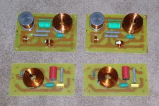
MK 5/6 Crossover PCB.
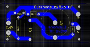
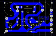
Here's the latest version of my Crossover PCB's. I decided to do separate boards for HF and MF/LF. Mainly because the etching tank was too small for a composite board but also to provide the opportunity to isolate the PCB's to avoid inductor crosstalk. All inductors and resistors and C1 are Jantzen. The bipolar electros are from Jaycar. Ozmosis's lovely MK 6 Elsinore build (seen elsewhere on this thread) was the catalyst for the redo of the PCB's but I was planning to do it anyway. I just needed a shove. I can't wait to hear his units as they have the new midwoofers. (by the way the Tweeter polarity is incorrectly shown on the HF PCB. I've corrected that since)
Here's the latest version of my Crossover PCB's. I decided to do separate boards for HF and MF/LF. Mainly because the etching tank was too small for a composite board but also to provide the opportunity to isolate the PCB's to avoid inductor crosstalk. All inductors and resistors and C1 are Jantzen. The bipolar electros are from Jaycar. Ozmosis's lovely MK 6 Elsinore build (seen elsewhere on this thread) was the catalyst for the redo of the PCB's but I was planning to do it anyway. I just needed a shove. I can't wait to hear his units as they have the new midwoofers. (by the way the Tweeter polarity is incorrectly shown on the HF PCB. I've corrected that since)
Attachments
Last edited:
Almost there...
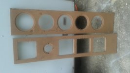
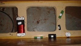
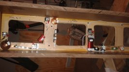
I laid out the xover's and started soldering them. I decided to put them inside the cabinets with removable panels from the driver openings. (see pics)
All I have left is cutting the port openings, installing the last two braces on the back panel, and assembling the cabinets.
Then another day in paint. I do auto paint & body so they should turn out nice. If I can the cabs done tomorrow I might start listening to them tomorrow night and paint them my next day off.
Check out the pics. I am waiting for the Audyn True Copper Cap to come back in stock, they only had one, so I got the Super caps...but check out the crazy difference in the size between those two caps.
L-1 is going in the bottom in case any one notices it's not in the pictures.
Joe...check your PM I have a quick question. Thanks.
Attachments
So close...
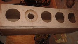
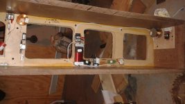
Man I am chomping at the bit...I have these things so close to being done save paint...but didn't quite get there...
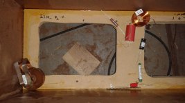
I have the crossovers installed and soldered, and all I have to do is install the front and back panels and connect the drivers.
I still need to do some sanding etc...but I'm hoping if I get home early one day this week I'l have them ready to paint in a couple hours.
Installed one driver to get an idea of what I need to do to install the binding posts and connections for the drivers....
Man I am chomping at the bit...I have these things so close to being done save paint...but didn't quite get there...
I have the crossovers installed and soldered, and all I have to do is install the front and back panels and connect the drivers.
I still need to do some sanding etc...but I'm hoping if I get home early one day this week I'l have them ready to paint in a couple hours.
Installed one driver to get an idea of what I need to do to install the binding posts and connections for the drivers....
Attachments
hi
i'm doing the mk 5 cross over
i come back to the project after 2 years off
i dont remember where to plug the big (air) 2 mh inductors
the xo parts lists 2 pairs of 2mh inductors
one pair is iron core and one is 'on air'
the big one (air) must go with the hf xo ?
or the lf xo?
thank for advice
dondiba
mk5 cross over precisions
hi Irext
thanks for your answer
ok, so
L1 is 2 mH, on air, for the tweeter
L6 is 2 mH too, for the bass, iron core
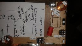
L3 is 0,33 mH according to this xo drawing, here attached...
or do you mean another xo drawing for mk5, for since this time some changes may have happened?
dondiba
hi Irext
thanks for your answer
ok, so
L1 is 2 mH, on air, for the tweeter
L6 is 2 mH too, for the bass, iron core
L3 is 0,33 mH according to this xo drawing, here attached...
or do you mean another xo drawing for mk5, for since this time some changes may have happened?
dondiba
Attachments
L3 can be either air cored or iron cored as it is very unlikely to be saturated. Same for MK6.
Same goes for L1. Basically because the 'leg' is 16 Ohm, it is up to eight times less likely to saturate compared to most other speakers.
Hi. There is no L6. L1 (1.8 or 2mh) should be air cored (feeds bottom pair of LF drivers). L3 (1.8 or 2mh) can be either air or iron cored (notch filter in series with C2 33mfd across tweeter). The schematic between MK5 and 6 has not changed, only some values. If you go to the Elsinore DIY web page it shows the schematic with the changed values from Mk5 to MK6 in red. For MK5 L3 is indeed .33mh. Hope this clears things up.
hi Irext
thanks for your answer
ok, so
L1 is 2 mH, on air, for the tweeter
L6 is 2 mH too, for the bass, iron core
L3 is 0,33 mH according to this xo drawing, here attached...
or do you mean another xo drawing for mk5, for since this time some changes may have happened?
dondiba
Hi Joe. Well I've just learned something. I always assumed L1 had to be air cored. Could have saved some space and cost. Never mind it's done now.")
Same goes for L1. Basically because the 'leg' is 16 Ohm, it is up to eight times less likely to saturate compared to most other speakers.
Hi Joe. Well I've just learned something. I always assumed L1 had to be air cored. Could have saved some space and cost. Never mind it's done now.
For L1, in recent times I have used the Jantzen P-Core 3.9mH 18AWG and it is only AUD $13.00 from speakerbug.com.au. They also have a heavier 15AWG for $22.00 - but being 16 Ohm, the less expensive is more than fine.

Cheers, Joe
Is it going to be this weekend?
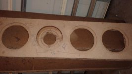
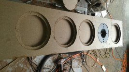
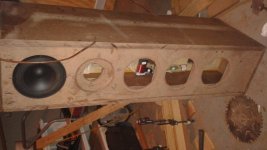
I'm done with all the internal wiring, and all I have left is to install the front and back panels and the stuffing, and paint them, and then install the drivers. I hope to get them painted tomorrow and have them ready to listen to Sunday.
I have really taken my time with these, as I laminated 3/8 in pieces together to make HDF paneling. Hopefully it's going to pay off.
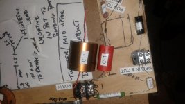
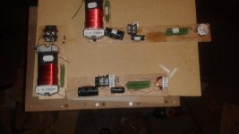
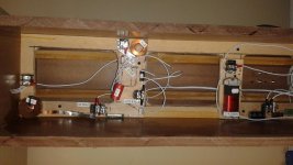
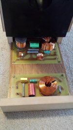
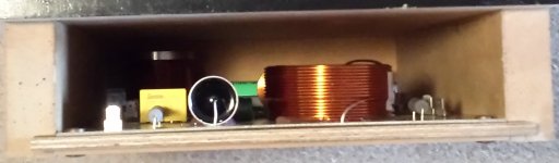
Here's the internal wiring. I haven't connected to the posts yet but they are ready to go. Man I am stoked.
Incidentally, the paneling was 3/8 of an inch, and I laminated 5 panels together for the body of the cabs, including the front brace and 4 panels for the front panel. 5 panels should have made the panels 15/16 of an inch. But once they were all glued together, and I got around to measuring them they are 13/16 of an inch. Hopefully that's close enough.
I'm done with all the internal wiring, and all I have left is to install the front and back panels and the stuffing, and paint them, and then install the drivers. I hope to get them painted tomorrow and have them ready to listen to Sunday.
I have really taken my time with these, as I laminated 3/8 in pieces together to make HDF paneling. Hopefully it's going to pay off.
Here's the internal wiring. I haven't connected to the posts yet but they are ready to go.
Man I am stoked.Incidentally, the paneling was 3/8 of an inch, and I laminated 5 panels together for the body of the cabs, including the front brace and 4 panels for the front panel. 5 panels should have made the panels 15/16 of an inch. But once they were all glued together, and I got around to measuring them they are 13/16 of an inch. Hopefully that's close enough.
Attachments
Here's the latest version of my Crossover PCB's. I decided to do separate boards for HF and MF/LF. Mainly because the etching tank was too small for a composite board but also to provide the opportunity to isolate the PCB's to avoid inductor crosstalk. All inductors and resistors and C1 are Jantzen. The bipolar electros are from Jaycar. Ozmosis's lovely MK 6 Elsinore build (seen elsewhere on this thread) was the catalyst for the redo of the PCB's but I was planning to do it anyway. I just needed a shove. I can't wait to hear his units as they have the new midwoofers. (by the way the Tweeter polarity is incorrectly shown on the HF PCB. I've corrected that since)
irext:
Will you be offering pcbs and, if so, can you give us an ETA?
Regards,
Scott
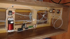
Crossovers done. Ready to be cabled. Very happy with the way they fit into the foot under the speaker.
Many many many thanks to irext for his time and skills developing the circuit boards and assemblege (is that a word)
Many many many thanks to irext for his time and skills developing the circuit boards and assemblege (is that a word)
Attachments
Elsinore Xover PCB's
I am going to get some prices for professionally etched PCB's. They are done on a panel basis so you fit as many boards as you can to a panel. At present I am etching them at home which gives a nice result but is quite labour intensive. For an outside company I simply give them the Protel file and the boards are sent to me. They can even have screen printed overlays etc at an extra cost. As for different components, I've designed them using Jantzen Inductors, resistors and for the C1 cap (Superior Z cap) which I feel is as good as they need to be and overkill in some areas. If you are going for foil inductors etc they will not fit and I have no real plans to do a PCB for them. Otherwise unless the components are vastly different in size they should fit. I have taken great pains to eliminate inductor crosstalk and as you can see separated the LF and HF sections to separate PCB's. So stay tuned and as soon as I get some quotes and work out costs I will post some prices. I hope you are O/K with this arrangement Joe R. I don't want to step on any toes.
Cheers.
irext:
I should have asked this in the last post: if you are going to make your Elsinore crossover pcbs available, is there any chance you could add pads at each location to permit the use of different components?
Much appreciated,
Scott
- Home
- Loudspeakers
- Multi-Way
- The "Elsinore Project" Thread