Hi Alan & all others. I sold my 66's in March 09, around pg 80 in this thread. Well I found a pair only 2 blocks from my new place, in 2015, & they are now being listened to as I type.
Just for chitter chat, they are unadulterated originals, teak fronts. Do not plan to to any upgrades on this set. work for me as is.
Just for chitter chat, they are unadulterated originals, teak fronts. Do not plan to to any upgrades on this set. work for me as is.
Your True Love !
Hi Doug ,
Hey ... so you could not live without Ditton 66s ! ... well those Yamaha PA speakers you mentioned previously certainly do not have sound like 66s.
You are fortunate to have now found a pair of 66s that give satisfactory listening without any reconditioning or modifications required.
If nothing is too worn out in them you will be hearing them as like their designers intended ... and which most Owners now have not , thus you may be fortunate indeed !
E-cap , not Alcap
Hi Doug ,
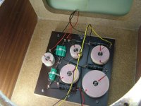
There is no C4 in your 66s.
Celestion stopped using the C4 , likely because it was causing crossover too low to the mid-dome.
C5 is the 24uF in your photo.
For C5 use ClarityCap PX 25uF.
"Madisound" still have stock of those.
Madisound also still have stock of ClarityCap PX in 3.9uF and 6uF for the tweeter circuit , and those will work better than the bunches of smaller values in parallel.
I would use ClarityCap PX 3.9uf plus the resistor as I originally advised you for C3 , but if you want to use an electrolytic cap there then use Mundorf E-Cap in their "PLAIN" series ,
because that is the closest to the original type that Celestion used.
Do not use the E-cap "RAW" because that is a lower quality capacitor construction and it will develop a leak sooner than the "PLAIN".
I would still use polypropylene caps for the woofer circuit , but if you want to use electrolytic caps then use Mundorf E-cap "PLAIN" 68uF for C2 , and E-caps "PLAIN" 56uF and 22uF in Parallel for C1 .
68uF with 10uF in Parallel would also work for C1 , but I think 56 with 22 will work better there.
Lay the 22uF along the top of the 56uF but slightly spaced from it , not touching it because two capacitor bodies touching when vibrated against each other by the sound pressure level inside the cabinets will cause microphonics which will be audible through the woofer as result of the Piezo-electric effects within each touching capacitor.
If you want them touching then put BluTak -{ Blu Tak }- between them to reduce fast vibration between their bodies.
"Partsconnexion" in Canada have the Mundorf E-Caps.
The "PLAIN" type are the lower voltage options.
The high voltage options are the "RAW" type which I do not recommend.
Click on each capacitor value and to open the page with its picture and look closely and you will see which ones have "Plain" printed on them and which ones have "Raw" printed on them.
There are no more "low-loss" Alcaps for 24uF or 72uF , and the available Alcaps for those values are etched foil caps which will develop leaks sooner than the low-loss type , thus I will not recommend the other Alcaps , and especially not for C5.
Hi Doug ,
There is no C4 in your 66s.
Celestion stopped using the C4 , likely because it was causing crossover too low to the mid-dome.
C5 is the 24uF in your photo.
For C5 use ClarityCap PX 25uF.
"Madisound" still have stock of those.
Madisound also still have stock of ClarityCap PX in 3.9uF and 6uF for the tweeter circuit , and those will work better than the bunches of smaller values in parallel.
I would use ClarityCap PX 3.9uf plus the resistor as I originally advised you for C3 , but if you want to use an electrolytic cap there then use Mundorf E-Cap in their "PLAIN" series ,
because that is the closest to the original type that Celestion used.
Do not use the E-cap "RAW" because that is a lower quality capacitor construction and it will develop a leak sooner than the "PLAIN".
I would still use polypropylene caps for the woofer circuit , but if you want to use electrolytic caps then use Mundorf E-cap "PLAIN" 68uF for C2 , and E-caps "PLAIN" 56uF and 22uF in Parallel for C1 .
68uF with 10uF in Parallel would also work for C1 , but I think 56 with 22 will work better there.
Lay the 22uF along the top of the 56uF but slightly spaced from it , not touching it because two capacitor bodies touching when vibrated against each other by the sound pressure level inside the cabinets will cause microphonics which will be audible through the woofer as result of the Piezo-electric effects within each touching capacitor.
If you want them touching then put BluTak -{ Blu Tak }- between them to reduce fast vibration between their bodies.
"Partsconnexion" in Canada have the Mundorf E-Caps.
The "PLAIN" type are the lower voltage options.
The high voltage options are the "RAW" type which I do not recommend.
Click on each capacitor value and to open the page with its picture and look closely and you will see which ones have "Plain" printed on them and which ones have "Raw" printed on them.
There are no more "low-loss" Alcaps for 24uF or 72uF , and the available Alcaps for those values are etched foil caps which will develop leaks sooner than the low-loss type , thus I will not recommend the other Alcaps , and especially not for C5.
Last edited:
alternate E-Cap option for woofer crossover filter
Hi again Doug ,
I have been thinking further after recommending connecting 56uF and 22uF in Parallel for C1 of the woofer filter to sum to 78uF there to compensate for the 68uF at C2.
Another option , and which I think may cause better audio result is to use three Mundorf E-Cap PLAIN in Parallel to sum to close to the original 72uF , and in particular use:
33uF + 22uF + 15uF in Parallel = 70uF , which is close enough to 72uF for the three in Parallel configuration to be used for both C1 and C2.
Electrolytic capacitors have significant colouration , and can be as a resonant narrow-band around a particular frequency area , thus if instead of using 1 electro cap use 3 of staggered values in Parallel so that the resonant colouration areas of each do not co-incide , hence will be a broad band-width of lower peak colouration.
Electrolytic caps have sufficient ESR to be able to connect them in Parallel without the Pulse Rise Times through each being significantly different ,
{ unlike with negligible ESR polypropylene caps } , thus for Listeners who prefer the audio characteristics of electrolytic caps I recommend trying the above configuration.
However if you want to stay with the simplest use of minimal parts , then use 68uF E-cap PLAIN for C2 , and 68uF + 8.2uF E-Cap PLAIN in Parallel for C1
- which I should have put in my last Post but I had not noticed the 8.2uF E-Cap PLAIN then.
{ I do not recommend staggered values connected in Parallel for polypropylene capacitors - I recommend using equal , or near equal , capacitances for Parallel connection of polypropylene capacitors.}
To fit into the narrow space on the 66 crossover board , stack the 3 capacitors with the 15uF laying on top of the 22uF laying on top of the 33uF , and with BluTak or Silicone tape in between their bodies to reduce contact resonances as I explained in my previous Post #1205 on this page.
Silicone tape is available for Electrical and Handy-man use in brand names such as "Rescue Tape".
After putting some between the capacitors , some more can be wrapped around the stack of the 3 to hold them securely , and then tie them to the circuit board with Nylon ties
-{ Not with metal wire , because looped wire will collect magnetic field by Induction from the nearby large Inductors and will then have an electric current circulating around the capacitors }.
With C3 in polypropylene connect 1.8 ohm 5 watt resistance in Series.
With C5 in polypropylene connect 1.5 ohm 5 watt resistance in Series.
Preferably use the Mills MRA-5 wirewounds I recommended previously in this thread ,
or try Mundorf's 5 watt MR5 metal oxide resistors if you don't want to use the Mills.
If there is still a little excess midrange after the above , then swap the resistances around and put the 1.8 ohm in Series with C5 and the 1.5 ohm in Series with C3.
Last edited:
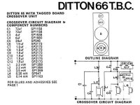
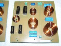
thinking of making a complete xover new board, so as to keep original.
c1 & c2 = Alcap 72uf
c3 = alcap 4uf
c5 = alcap LL 12uf ( x2) in parallel
c6,7,8 = clarity px 3.9uf
c9,10,11,12 = clarity px 2.2uf & 3.9 in parallel
roughly 40 -50 dollars (CA) for 5 new inductors . parts express have Jantzen at more cost than Madisound brand.
thoughts?
c1 & c2 = Alcap 72uf
c3 = alcap 4uf
c5 = alcap LL 12uf ( x2) in parallel
c6,7,8 = clarity px 3.9uf
c9,10,11,12 = clarity px 2.2uf & 3.9 in parallel
roughly 40 -50 dollars (CA) for 5 new inductors . parts express have Jantzen at more cost than Madisound brand.
thoughts?
New Crossover Board , and other matters
Hi Doug ,
several points , as follows:
(1)- if you are going to make new crossover boards , and buy new inductors ,
then you may as well do the job in such way as to minimize the magnetic coupling between the inductors because that will give clearer sound.
Go back to Page 103 and read in my Post #1022 about options of Sizes for the board , and next about where and how to place the components on the board.
(2)- Jantzen brand inductors cost more because of how they are manufactured , and also because they are imported from Europe.
The Madisound branded inductors seem to be made by Solen who are in Canada thus less shipping cost to Madisound.
If they are not made by Solen then they are made by someone who is copying the Solen design.
(3)- For tweeter inducter , L5 0.14mH , buy one that has between 0.4 ohm and 0.5 ohm DCR but not higher DCR, because a small amount of resistance is needed in the circuit there.
{ Ideally 0.4 ohm }.
For midrange inductor , L1 2.2mH , buy one that has DCR of 1.2 ohm DCR or very slightly higher but preferably not as high as 1.5 ohm , because DCR is critical there and Celestion's original inductor there has the optimum DCR.
For the other Inductors buy with as low DCR as you can afford so that maximum of the wanted signal is not lost in DCR in those.
That is you will then have a physically larger size coil for L2 2.2mH than for L1 , and L3 will be physically very large.
The reasons for the above are that for inductors connected in Series with drivers usually one does not want to lose the wanted part of the signal in resistance ,
but for inductors connected in Parallel with drivers a small amount of DCR reduces the electrical resonance of the crossover circuit and driver combination - very low DCR inductors there often cause worse sound.
Celestion used the significant DCRs inductors for L2 and L3 because those cost less than lower DCR inductors , and most importantly because when the 66s were made most Amplifiers would not drive 4 ohm loads to high volume levels , but now modern amplifier designs allow for higher volume levels driving 4 ohm loads , thus unless you are are using a vintage amplifier install lower DCR inductors for L2 and L3 and you will get a clearer defined bass sound.
Use Nylon or Plastic bolts or cable ties to hold the inductors onto the board.
Do not use Steel bolts , and preferably not any type of Metal bolts , because metal through the centre of the inductors is effectively a core and thereby increases the Inductance , and also it causes early Saturation which causes muddy sound.
(4)- Madisound have ClarityCap in 6uf.
Use that instead of 3.9uF + 2.2uF in Parallel , because the single cap there will give clearer sound.
(5)- As you have decided to use Alcaps in the midrange and woofer sections , then use a 3.9uF or 4uF LL Alcap for C3 because it will have longer service life than the non-LL types , and probably will give clearer sound.
(6)- Two of 12uF LL Alcaps in Parallel will work for C5 if you do the soldering very neatly at each end , and also not wind the caps' leads around each other but simply solder both together at the single point where each connects to the next component of the crossover.
Scrape clean the relevant section of their leads before you solder so that there is no remains of the oxide which forms on all leads during storage after manufacture.
(7)- As you have decided to use Alcaps for C1 and C2 then you will hear what these do to the sound , and as they are low price you will not have lost too much money if you decide you do not like their sound.
Last edited:
Burn In
Hi Doug ,
Bipolar electrolytic capacitors require a period of use for their electrodes to chemically form - that is part of what is sometimes referred to as "Burning In".
As such , the 66s after new Alcaps installed will likely sound a bit rough or slightly distorted for the first few hours of use , and maybe for a while longer.
To form the electrodes in the Alcaps play the loudspeakers for more than 1 hour per day every day until the sound becomes the same from one day to the next.
Next , the chemically formed electrodes deteriorate when there is no signal , thus the longer you leave the speakers not played the more their sound will deteriorate.
If the Alcaps are not faulty or part-faulty it may be about 2 weeks of no playing before you notice deterioration of sound.
Several loudspeakers which have electrolytic caps in their crossovers that I have listened to after periods of no use always sounded rough and slightly distorted until after more than a week of regular daily playing.
That is one reason I do not use electrolytic caps in loudspeakers that I modify.
After you have used your new Alcaps for about 2 weeks Post here and report to us any changes of sound you have noticed during the listening period.
A little late to the party, but I've been a Ditton 66 owner for more than a decade. I currently own 3 pairs but I will be moving 1 on shortly as 3 pairs is the height of greed!  .
.
The two pairs that I'm keeping, the first I fully restored in 2015 and the second I fully restored in 2018. I documented the restorations in detail on another forum. I hope I'm allowed to link to it because it would be too much work to re-post / re-upload everything here. (BTW I have no professional training or experience so the refurbishments were a very steep learning curve!) I'd be grateful for comments on my refurbishments:
An Epic Tale Of Two Celestion Ditton 66 Refurbishments
I have a huge soft-spot for the 66s, but I cringe when I measure their frequency response and see how coloured they are! I use parametric EQ to reduce the output between 300Hz-1.25kHz as I find this really helps to clean up the sound.
As shown in the graphs in the above link, there are differences in the FR between my 2015 and 2018 projects between 400Hz-1kHz and was wondering if this is purely because the 2015 uses T1600 and MF500 while the 2018 uses T2619 and MD500, or could it also be due to manufacturing tolerance differences between inductors on the crossovers? My 2015 and 2018 66's both use the TBC (point-to-point) version of the crossover.
The differences in FR above 5kHz are much easier to explain, every HF2000 I tested had a significantly different HF response, and I didn't know what the 'target' HF response was supposed to be! So for the 2015 project I simply selected the first two HF2000s that sounded well-matched to my ears. For the 2018 project I selected the two HF2000s that measured closest to flat. I discuss the extent of the divergences in HF2000 response in the following thread:
Another Celestion Ditton 66 Renovation thread
Finally, I have recently been reading about the importance of impulse response (I've never paid attention to this previously), and was therefore wondering what the 66's IR should look like? This is the step response of one 66 measured from my listening position with the mic at the height of the MD500:
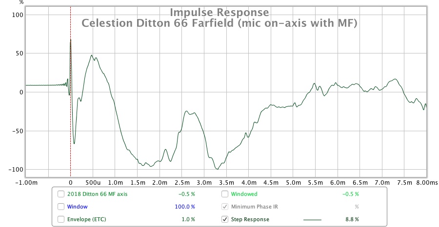
I don't really know how to interpret IR graphs, but compared to my Tannoy MG12, the Celestion's IR doesn't look too good. I wonder if DSP software like Dirac would correct the IR, or is it not possible to electrically correct the IR of a speaker system that uses a passive bass radiator?

. The two pairs that I'm keeping, the first I fully restored in 2015 and the second I fully restored in 2018. I documented the restorations in detail on another forum. I hope I'm allowed to link to it because it would be too much work to re-post / re-upload everything here. (BTW I have no professional training or experience so the refurbishments were a very steep learning curve!) I'd be grateful for comments on my refurbishments:
An Epic Tale Of Two Celestion Ditton 66 Refurbishments
I have a huge soft-spot for the 66s, but I cringe when I measure their frequency response and see how coloured they are! I use parametric EQ to reduce the output between 300Hz-1.25kHz as I find this really helps to clean up the sound.
As shown in the graphs in the above link, there are differences in the FR between my 2015 and 2018 projects between 400Hz-1kHz and was wondering if this is purely because the 2015 uses T1600 and MF500 while the 2018 uses T2619 and MD500, or could it also be due to manufacturing tolerance differences between inductors on the crossovers? My 2015 and 2018 66's both use the TBC (point-to-point) version of the crossover.
The differences in FR above 5kHz are much easier to explain, every HF2000 I tested had a significantly different HF response, and I didn't know what the 'target' HF response was supposed to be! So for the 2015 project I simply selected the first two HF2000s that sounded well-matched to my ears. For the 2018 project I selected the two HF2000s that measured closest to flat. I discuss the extent of the divergences in HF2000 response in the following thread:
Another Celestion Ditton 66 Renovation thread
Finally, I have recently been reading about the importance of impulse response (I've never paid attention to this previously), and was therefore wondering what the 66's IR should look like? This is the step response of one 66 measured from my listening position with the mic at the height of the MD500:
I don't really know how to interpret IR graphs, but compared to my Tannoy MG12, the Celestion's IR doesn't look too good. I wonder if DSP software like Dirac would correct the IR, or is it not possible to electrically correct the IR of a speaker system that uses a passive bass radiator?
Last edited:
Celestion MF500 vs MD500
Is this thread still active? I'm trying to get to the heart of the sonic differences between the MF500 and MD500 domed mid units.
AFAIK, Celestion first introduced the MF500 with 50W power handling and later replaced it with the MD500 with increased 80W power handling.
Apparently the two units had slightly different frequency responses, I've read that the MD500 has stronger mid frequencies but rolls off sooner at the bottom and top.
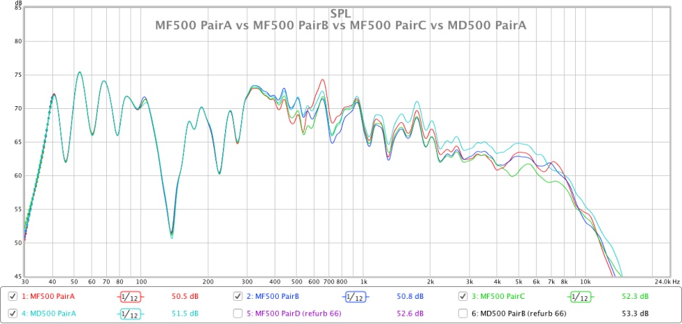
Having measured a selection of MF500 and MD500 units (in free-space without a baffle), I have found MF500 units that have identical frequency response to MD500 units, MF500 units that have different responses to other MF500 units, and MD500 units that have different responses to other MD500 units. I am therefore unable to conclude with certainty that the MF500 and MD500 have different tunings.
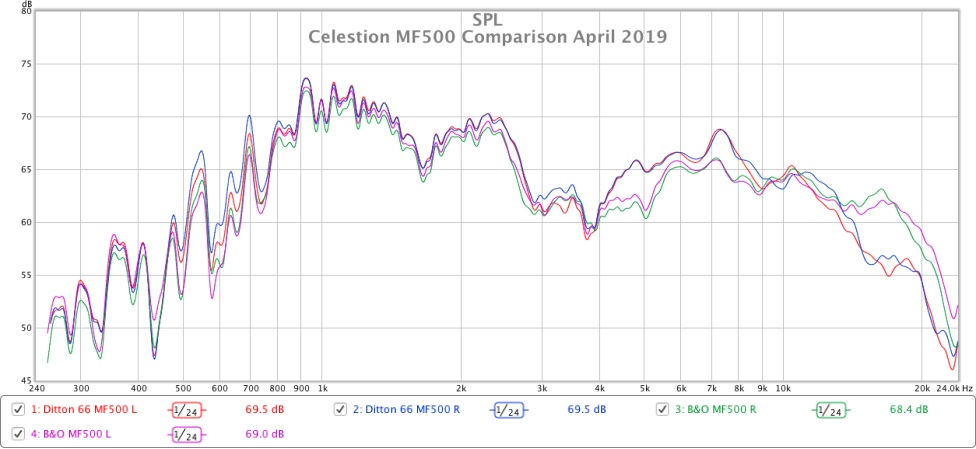
Here is one example comparing two different pairs of MF500. The measurements were made in free space without any baffle (the driver was placed on the carpet facing the ceiling and the mic was positioned 1 metre above it):
Has anyone else taken measurements of multiple pairs of MF500 and MD500 units? It would be good to compare notes.
Possible explanations?
- Perhaps there was a there was a transition period during which Celestion mis-labelled MD500 units as MF500.
- Perhaps there was originally inherent and unavoidable manufacturing variation in MF500 and MD500 units.
- Perhaps the ageing process / deterioration is responsible for the apparently different tunings between the MF500 and MD500.
- Perhaps Celestion made a different tuning of MF500 for other loudspeaker makers e.g. B&O.
The following graph compares the overall system responses of two pairs of Ditton 66 I have rebuilt. The one labelled '2015' uses T1600 bass units, MF500 mids and 30uf in the MF circuit. The one labelled '2018' uses T2169 bass units, MD500 mids and 24uf in the MF circuit.
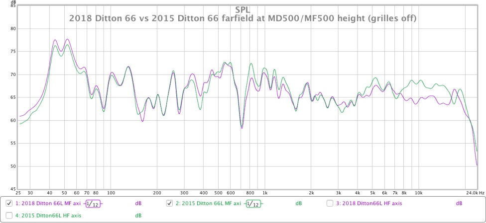
The measurements were taken at my listening seat, not in an anechoic chamber, so there are lots of peaks and dips in the response, but the two speakers were measured in the exact same location, so the results can be compared with confidence.
I also took nearfield measurements from 1 metre distance:

According to the measurements, the 66 with the MF500 has stronger output from 750Hz to 1.5kHz while the 66 with the MD500 has stronger output from 300Hz to 500Hz. There is almost zero difference in the response between 2kHz and 4kHz. The difference in HF output above 4kHz is purely due to variations in the HF2000 units used. (I measured a total of 13 different HF2000 units and found huge differences in their response!).
Is this thread still active? I'm trying to get to the heart of the sonic differences between the MF500 and MD500 domed mid units.
AFAIK, Celestion first introduced the MF500 with 50W power handling and later replaced it with the MD500 with increased 80W power handling.
Apparently the two units had slightly different frequency responses, I've read that the MD500 has stronger mid frequencies but rolls off sooner at the bottom and top.
Having measured a selection of MF500 and MD500 units (in free-space without a baffle), I have found MF500 units that have identical frequency response to MD500 units, MF500 units that have different responses to other MF500 units, and MD500 units that have different responses to other MD500 units. I am therefore unable to conclude with certainty that the MF500 and MD500 have different tunings.
Here is one example comparing two different pairs of MF500. The measurements were made in free space without any baffle (the driver was placed on the carpet facing the ceiling and the mic was positioned 1 metre above it):
Has anyone else taken measurements of multiple pairs of MF500 and MD500 units? It would be good to compare notes.
Possible explanations?
- Perhaps there was a there was a transition period during which Celestion mis-labelled MD500 units as MF500.
- Perhaps there was originally inherent and unavoidable manufacturing variation in MF500 and MD500 units.
- Perhaps the ageing process / deterioration is responsible for the apparently different tunings between the MF500 and MD500.
- Perhaps Celestion made a different tuning of MF500 for other loudspeaker makers e.g. B&O.
The following graph compares the overall system responses of two pairs of Ditton 66 I have rebuilt. The one labelled '2015' uses T1600 bass units, MF500 mids and 30uf in the MF circuit. The one labelled '2018' uses T2169 bass units, MD500 mids and 24uf in the MF circuit.
The measurements were taken at my listening seat, not in an anechoic chamber, so there are lots of peaks and dips in the response, but the two speakers were measured in the exact same location, so the results can be compared with confidence.
I also took nearfield measurements from 1 metre distance:
According to the measurements, the 66 with the MF500 has stronger output from 750Hz to 1.5kHz while the 66 with the MD500 has stronger output from 300Hz to 500Hz. There is almost zero difference in the response between 2kHz and 4kHz. The difference in HF output above 4kHz is purely due to variations in the HF2000 units used. (I measured a total of 13 different HF2000 units and found huge differences in their response!).
Last edited:
Celestion MF500 vs MD500
I haven’t noticed any sonic differences between my MF500 and MD500 drivers. My 66s were purchased new in about 1974-75 and when I opened them up a few years ago to do some tests I noted one had an MF500 and the other a MD500. One speaker had been taken back for a repair to a woofer in about 1977 but I don’t think there was anything done to the midranges at that time. If they had replaced the MF500 with an MD500 I’m sure I would have remembered.
The cross-overs have been modified as per this thread. Some time ago when I did some listening tests I noticed that my R speaker appeared a little louder than the L so I added a 83R across the MF500 in the R, as advised in this thread, and it did center the sound of a countertenor’s voice which was slightly off centre. This advice was due to some results I posted on the individual driver impedances & FR. However, the FR tests were done in the near field so those results may not be accurate for the higher frequencies.
More recently, after researching the test methods, I tested a pair of MF500 drivers in their diy box. Each box contains a MF500 and a tweeter and is narrower at the top (5” wide) than the bottom (12” wide) with an overall height of about 13”. During testing they were located on and flush with the front of a diy woofer box and were about 28” above the floor. I don’t know the history of these MF500 units. The mic was either 30”, 36” or 1m from the speaker. I think I decided to use 30” for future tests. I was experimenting with my testing hardware and the various software packages at the time of the MF500 tests and the FR results are shown below.
The first FR chart is from HOLMImpulse.

The second chart from REW

The third from SpeakerWorkshop

The various software packages show similar results. The output from the L driver is generally about 1.5-2db higher than the R driver in the higher and lower frequencies. This seems to be greater than the differences shown in your chart for the two individual pairs. My drivers have peaks at about 1kHz (similar to yours) & 3 kHz (yours are closer to 2kHz) and a dip at about 2kHz (yours are about 1.5kHz). I don’t know if the different testing conditions have influenced the results.
The next chart shows the impedance for the MF500 pair using SpeakerWorkshop. The DCR of the L speaker was 6.3R and the R 6.4R.

The next chart shows the impedance for the mids in the 66s.

The 66 mids DCRs are 7.3R for the MF500 and 6.3R for the MD500 so the 66 MF500 is 1R greater than the other mid units which are all about 6.3R. Others have posted the DCRs for their speakers earlier on in this thread.
I did some overall FRs of the 66’s and will take a look at those and post them later.
I haven’t noticed any sonic differences between my MF500 and MD500 drivers. My 66s were purchased new in about 1974-75 and when I opened them up a few years ago to do some tests I noted one had an MF500 and the other a MD500. One speaker had been taken back for a repair to a woofer in about 1977 but I don’t think there was anything done to the midranges at that time. If they had replaced the MF500 with an MD500 I’m sure I would have remembered.
The cross-overs have been modified as per this thread. Some time ago when I did some listening tests I noticed that my R speaker appeared a little louder than the L so I added a 83R across the MF500 in the R, as advised in this thread, and it did center the sound of a countertenor’s voice which was slightly off centre. This advice was due to some results I posted on the individual driver impedances & FR. However, the FR tests were done in the near field so those results may not be accurate for the higher frequencies.
More recently, after researching the test methods, I tested a pair of MF500 drivers in their diy box. Each box contains a MF500 and a tweeter and is narrower at the top (5” wide) than the bottom (12” wide) with an overall height of about 13”. During testing they were located on and flush with the front of a diy woofer box and were about 28” above the floor. I don’t know the history of these MF500 units. The mic was either 30”, 36” or 1m from the speaker. I think I decided to use 30” for future tests. I was experimenting with my testing hardware and the various software packages at the time of the MF500 tests and the FR results are shown below.
The first FR chart is from HOLMImpulse.
The second chart from REW
The third from SpeakerWorkshop
The various software packages show similar results. The output from the L driver is generally about 1.5-2db higher than the R driver in the higher and lower frequencies. This seems to be greater than the differences shown in your chart for the two individual pairs. My drivers have peaks at about 1kHz (similar to yours) & 3 kHz (yours are closer to 2kHz) and a dip at about 2kHz (yours are about 1.5kHz). I don’t know if the different testing conditions have influenced the results.
The next chart shows the impedance for the MF500 pair using SpeakerWorkshop. The DCR of the L speaker was 6.3R and the R 6.4R.
The next chart shows the impedance for the mids in the 66s.
The 66 mids DCRs are 7.3R for the MF500 and 6.3R for the MD500 so the 66 MF500 is 1R greater than the other mid units which are all about 6.3R. Others have posted the DCRs for their speakers earlier on in this thread.
I did some overall FRs of the 66’s and will take a look at those and post them later.
That's really helpful information, thank you for taking the time to post.
I am now in the process of refurbishing my 3rd pair of 66s, so have taken the opportunity to measure every spare MF500 and MD500 I have in my stock cupboard when it's actually installed in the 66 baffle, as this should provide a more accurate measurement of its response in use.
The following graph compares the response of an MF500 measured in free space without crossover, with that of the same MF500 installed in the 66 enclosure and connected to the crossover. It is evident that the baffle provides higher output from 500Hz-900Hz and lower output from 1kHz-3kHz compared to measuring the driver in free space:
The next graph shows the respective low-pass and high-pass slopes of the T1600 and MF500 when installed in the 66 enclosure and connected to the crossover:
With the T1600 still part of the circuit, the following graph compares the respective responses of all the spare MF500 and MD500 units I have. The left and right units from each 'pair' measured very closely (the best match was less than 0.25dB difference across most of the operating range, the worst match was just over 0.5dB difference across most of the operating range), so to prevent overcrowding the graph I have only included one unit from each pair:
This final graph also includes an MF500 and MD500 from my respective 2015 and 2018 refurbs. I did not wish to disturb these drivers so I just measured them in the cabinets they were already installed in, so please ignore the frequencies above 4kHz:
I am now in the process of refurbishing my 3rd pair of 66s, so have taken the opportunity to measure every spare MF500 and MD500 I have in my stock cupboard when it's actually installed in the 66 baffle, as this should provide a more accurate measurement of its response in use.
The following graph compares the response of an MF500 measured in free space without crossover, with that of the same MF500 installed in the 66 enclosure and connected to the crossover. It is evident that the baffle provides higher output from 500Hz-900Hz and lower output from 1kHz-3kHz compared to measuring the driver in free space:
An externally hosted image should be here but it was not working when we last tested it.
The next graph shows the respective low-pass and high-pass slopes of the T1600 and MF500 when installed in the 66 enclosure and connected to the crossover:
An externally hosted image should be here but it was not working when we last tested it.
With the T1600 still part of the circuit, the following graph compares the respective responses of all the spare MF500 and MD500 units I have. The left and right units from each 'pair' measured very closely (the best match was less than 0.25dB difference across most of the operating range, the worst match was just over 0.5dB difference across most of the operating range), so to prevent overcrowding the graph I have only included one unit from each pair:
An externally hosted image should be here but it was not working when we last tested it.
This final graph also includes an MF500 and MD500 from my respective 2015 and 2018 refurbs. I did not wish to disturb these drivers so I just measured them in the cabinets they were already installed in, so please ignore the frequencies above 4kHz:
An externally hosted image should be here but it was not working when we last tested it.
Last edited:
I am wondering if I should replace my totally all original xovers with these that I found in England?
Anyone heard, seen or use these.?
I would keep the originals for sure.
I have a MD 500 that is measuring only 3.6 ohms. (spare unit) Is it usable at that low of R ? &/or is it refurbishable to get back to 6 plus ohms?
Anyone heard, seen or use these.?
I would keep the originals for sure.
I have a MD 500 that is measuring only 3.6 ohms. (spare unit) Is it usable at that low of R ? &/or is it refurbishable to get back to 6 plus ohms?
Attachments
Celestion 66 FR tests
These charts are from tests on my 66s using ARTA software and 1/3 octave smoothed. Gate was 10,10.5 mS so good from about 100Hz. Mic distance was around 30-36" with the speakers on the floor with bubble foam on the floor between the speakers and the mic and as far from walls as possible. Used calibrated mic and amplifiers. Grills were removed.
The crossovers were modified as per this thread including the 82R across the R mid driver.
The output levels for the two speakers were slightly different with the R speaker set about 2 db higher than the L during these tests (accidentally touched the gain control and didn't want to repeat all the tests as I was actually evaluating the various software packages at the time)
The only area of significant difference between the two speakers appears to be to be in the very high frequencies with the L having a slightly higher output.


Celestion 66 Step Response
ToTo Man posted a Step Response from his listening position for a Celestion 66 earlier in this thread and asked if the result was typical. Someone with experience in this area may be able to offer an opinion as I am completely new to it. Linkwitz Lab has an interesting discussion of speaker step response, including for 3-ways, at item F on this page: Frontiers
I've generated the Step Responses using REW for the FR tests on my 66s I posted earlier today. The first two charts show the response over 8ms as per ToTo Man's chart. My tests were done with the mic about 1m from the speaker.


Not much difference between these two but different from the one posted by ToTo Man. Different testing methods perhaps.
To get the full picture of the woofer response as shown in the 3-way in the Linkwitz article I expanded the X axis to 20ms. These are shown below


ToTo Man posted a Step Response from his listening position for a Celestion 66 earlier in this thread and asked if the result was typical. Someone with experience in this area may be able to offer an opinion as I am completely new to it. Linkwitz Lab has an interesting discussion of speaker step response, including for 3-ways, at item F on this page: Frontiers
I've generated the Step Responses using REW for the FR tests on my 66s I posted earlier today. The first two charts show the response over 8ms as per ToTo Man's chart. My tests were done with the mic about 1m from the speaker.
Not much difference between these two but different from the one posted by ToTo Man. Different testing methods perhaps.
To get the full picture of the woofer response as shown in the 3-way in the Linkwitz article I expanded the X axis to 20ms. These are shown below
- Status
- This old topic is closed. If you want to reopen this topic, contact a moderator using the "Report Post" button.
- Home
- Loudspeakers
- Multi-Way
- Celestion 66 needs mid-range