Thomas,1. Since the geometry of the Beyma faceplate allows me to place the midrange, thus the mid-holes very close to the throat, why not just use one 2” compression driver >500Hz. Are compression mid-drivers just plain no-no? (I have a pair of Community M200 + JBL 2482 on layaway)
2. Why not use a pair of large, say 3” dome midranges, is this related to dome geometry?
3. Is the Beyma a bad choice altogether, Synergy-wise?
1. A single compression driver in an offset mounting will not "illuminate" the horn area, dispersion will not be uniform.
The distance from the 2482 diaphragm to the exit is around 90mm, the HF would need to be delayed to compensate for the added path length of the mid driver.
A 2482 would still need another pair of drivers between it and the LF.
2.The contained volume between the cone and the exit port makes an acoustic low pass filter, domes would make for a more difficult construction.
Most domes have little excursion, so output would be less than cones typically used for midrange in a Synergy horn.
3.Considering a compression driver would load better, have greater sensitivity, and cost less, one could say that the Beyma TPL-150 AMT is not a good choice.
Tape together a cardboard horn of the desired dispersion pattern and see how well (or poorly) the TPL-150 does in it.
If it does well, consider using a pair of 6.5" cones for the mids, then all you would need to complete the system would be sub woofers, which could be in separate cabinets.
Art
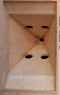
In the horn pictured below, there is one HF driver at the horn throat, four mid cones with two exit holes for each, and two low cones, also with a pair of exit holes.12 hf drivers in one horn. that's a wow!
Tom Danley's layered combiner does allow for multiple HF drivers on a single horn, but multiple HF drivers are not generally required for home use other than for persons with severe hearing impairment
") .
.Art
Attachments
Patrick,Come to think of it, another interesting option might be to simply subdivide a Unity horn into four horns. For instance, instead of using a Unity horn that measures 50 degrees by 50 degrees, one might use *four* Unity horns that are each 25 degrees by 25 degrees.
Your "simple" option would require four times the cabinet work, and four times the drivers as a normal Synergy horn uses for the same coverage.
In addition to that complexity and expense, to avoid comb filtering the four horns need to be angled away from each other in both the vertical and horizontal planes, requiring some rather "interesting" filler pieces between the mouths.
And though if done perfectly, four conical horns can provide fairly "seamless" coverage, believe me (I have tried it) a single conical horn of the same coverage angle will have more even coverage.
Art
Thank you, Art.
What a shame, I kinda liked the idea of compression mids. It should be noted that I intend to do a 3-way Synergy, I'm just starting from the top!
Hmm, that eliminates the use of domes...
I already have a pair of TPL's so price is somewhat unimportant. Having build a pair of 7Pi cornerhorns with the well regarded B&C DE250 compression driver I must say that the Beyma is just in another league. I have owned several pairs of speakers which employs compression driver tweeters, and they're just not of my taste. They fail in the naturalness and resolution department compared to the AMT.
I've modelled with the closed back Eminence LA6-CBMR, and it looks good. My only concern is that the model show best performance with very small holes (~2x10mm = ~2x4cm^2). I'm worried that it will sound squeezed when forcing
133cm^2 through the small band-pass holes?
/Thomas
Thomas,
1. A single compression driver in an offset mounting will not "illuminate" the horn area, dispersion will not be uniform.
The distance from the 2482 diaphragm to the exit is around 90mm, the HF would need to be delayed to compensate for the added path length of the mid driver.
A 2482 would still need another pair of drivers between it and the LF.
What a shame, I kinda liked the idea of compression mids. It should be noted that I intend to do a 3-way Synergy, I'm just starting from the top!
2.The contained volume between the cone and the exit port makes an acoustic low pass filter, domes would make for a more difficult construction.
Most domes have little excursion, so output would be less than cones typically used for midrange in a Synergy horn.
Hmm, that eliminates the use of domes...
3.Considering a compression driver would load better, have greater sensitivity, and cost less, one could say that the Beyma TPL-150 AMT is not a good choice.
Tape together a cardboard horn of the desired dispersion pattern and see how well (or poorly) the TPL-150 does in it.
If it does well, consider using a pair of 6.5" cones for the mids, then all you would need to complete the system would be sub woofers, which could be in separate cabinets.
I already have a pair of TPL's so price is somewhat unimportant. Having build a pair of 7Pi cornerhorns with the well regarded B&C DE250 compression driver I must say that the Beyma is just in another league. I have owned several pairs of speakers which employs compression driver tweeters, and they're just not of my taste. They fail in the naturalness and resolution department compared to the AMT.
I've modelled with the closed back Eminence LA6-CBMR, and it looks good. My only concern is that the model show best performance with very small holes (~2x10mm = ~2x4cm^2). I'm worried that it will sound squeezed when forcing
133cm^2 through the small band-pass holes?
/Thomas
Last edited:
Thomas,Thank you, Art.
What a shame, I kinda liked the idea of compression mids. It should be noted that I intend to do a 3-way Synergy, I'm just starting from the top!
I've modelled with the closed back Eminence LA6-CBMR, and it looks good. My only concern is that the model show best performance with very small holes (~2x10mm = ~2x4cm^2). I'm worried that it will sound squeezed when forcing
133cm^2 through the small band-pass holes?
Cone drivers on an offset horn are "compression drivers" though they don't usually have as high of a compression ratio as most HF compression drivers (less "squeezing"). You are proposing a compression ratio of 16/1 (higher than most HF compression drivers) for the LA6-CBMR, at high power levels that would probably break the cone.
I am using Eminence Alpha 8" and 6" with relatively small (less than a 5/1 compression ratio) exit holes, they sound and measure well.
I'm not sure what a "squeezed" sound would look or measure like though...
Art
Attachments
Are you sure?
Off the top of my head, here's the cost of a couple of options.
The first option is the 'traditional' one; it uses a three way Unity horn to cover nine octaves:
Lambda Unity Horn
tweeter : B&C DE25 ($125)
midrange : 4 x Misco JC5RTF-B ($120)
woofer : Lambda something-or-another ($200)
crossover : very complex three way crossover. Minimum $100 per channel
total : $545 per channel, plus a big ol' cabinet
versus
Yorkville PSA1
tweeter : dual BMS 4550 ($300)
midrange/woofer : 4 x 18 Sound 6ND430 ($600)
crossover : relatively simple two-way DSP xover. $100 per channel.
Total : $1000
Admittedly, the Paraline option is more expensive. By almost a hundred percent.
But it's also simpler for the DIY'er, and it's smaller.
I have a PILE of Unity horns in the garage that just didn't work.
I'm not 100% sure that my idea will work, but if I'm correct, it seems that we can reduce the complexity of a Untiy horn from a three-way to a two-way, and I think that will be a lot easier to get right. The passive xover in a Unity horn is fairly hideous to get right.
I think the easiest way to reduce the cost of the second option is to use a midrange with much lower power handling. The main reason the 18Sound midranges cost $150 a pop is that they handle very high power. (I wonder if Yorkville has their own version of the 6ND430? I noticed that their speaker is rated for lower power than the driver that's for sale at ussspeaker.com (Eighteen Sound Speakers - 18 Sound speakers - Eighteen Sound speaker partss - 18 Sound woofers, 18 Sound high frequency drivers and 18 Sound lightweight neodymium low frequency woofers and midrange speakers available here. 18 Sound speaker components))
Off the top of my head, here's the cost of a couple of options.
The first option is the 'traditional' one; it uses a three way Unity horn to cover nine octaves:
Lambda Unity Horn
tweeter : B&C DE25 ($125)
midrange : 4 x Misco JC5RTF-B ($120)
woofer : Lambda something-or-another ($200)
crossover : very complex three way crossover. Minimum $100 per channel
total : $545 per channel, plus a big ol' cabinet
versus
An externally hosted image should be here but it was not working when we last tested it.
An externally hosted image should be here but it was not working when we last tested it.
Yorkville PSA1
tweeter : dual BMS 4550 ($300)
midrange/woofer : 4 x 18 Sound 6ND430 ($600)
crossover : relatively simple two-way DSP xover. $100 per channel.
Total : $1000
Admittedly, the Paraline option is more expensive. By almost a hundred percent.
But it's also simpler for the DIY'er, and it's smaller.
I have a PILE of Unity horns in the garage that just didn't work.
I'm not 100% sure that my idea will work, but if I'm correct, it seems that we can reduce the complexity of a Untiy horn from a three-way to a two-way, and I think that will be a lot easier to get right. The passive xover in a Unity horn is fairly hideous to get right.
I think the easiest way to reduce the cost of the second option is to use a midrange with much lower power handling. The main reason the 18Sound midranges cost $150 a pop is that they handle very high power. (I wonder if Yorkville has their own version of the 6ND430? I noticed that their speaker is rated for lower power than the driver that's for sale at ussspeaker.com (Eighteen Sound Speakers - 18 Sound speakers - Eighteen Sound speaker partss - 18 Sound woofers, 18 Sound high frequency drivers and 18 Sound lightweight neodymium low frequency woofers and midrange speakers available here. 18 Sound speaker components))
Thanks Art!
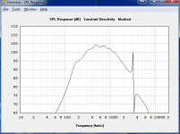
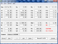
Maybe I'm doing it wrong, with 5/1 ratio my sims look like (see pics). The larger entry hole/s also gives me a spike at ~3000Hz.
ObviouslyThomas,
Cone drivers on an offset horn are "compression drivers."
I am using Eminence Alpha 8" and 6" with relatively small (less than a 5/1 compression ratio) exit holes, they sound and measure well.
Maybe I'm doing it wrong, with 5/1 ratio my sims look like (see pics). The larger entry hole/s also gives me a spike at ~3000Hz.
Attachments
Originally Posted by weltersys
Patrick,
Your "simple" option would require four times the cabinet work, and four times the drivers as a normal Synergy horn uses for the same coverage.
In addition to that complexity and expense, to avoid comb filtering the four horns need to be angled away from each other in both the vertical and horizontal planes, requiring some rather "interesting" filler pieces between the mouths.
And though if done perfectly, four conical horns can provide fairly "seamless" coverage, believe me (I have tried it) a single conical horn of the same coverage angle will have more even coverage.
Art
Having built both types, I am also quite sure that a simple square or rectangular conical horn is far simpler to build, takes up about an inch less depth and has much smoother frequency response, and more extended HF than a Paraline.
I am also sure that most any single 1" exit driver with diaphragms in the 1.5 to 1.75 inch diameter range is more than capable of clean response down to the point where they are fully usable with a pair of 6.5" or even 8" cones for home use level on a horn with an exit size of around 2 x 2 foot.
Using two cones and a 1" compression driver, driver costs for the above 100 Hz range could be less than $200, with sub woofers added per taste.
Art
Patrick,
Your "simple" option would require four times the cabinet work, and four times the drivers as a normal Synergy horn uses for the same coverage.
In addition to that complexity and expense, to avoid comb filtering the four horns need to be angled away from each other in both the vertical and horizontal planes, requiring some rather "interesting" filler pieces between the mouths.
And though if done perfectly, four conical horns can provide fairly "seamless" coverage, believe me (I have tried it) a single conical horn of the same coverage angle will have more even coverage.
Art
Yes, I'm sure. I converted my PA from multiple narrow conical horns to 90 degree horizontal conical horns, the coverage is far more smooth now.Are you sure?
Having built both types, I am also quite sure that a simple square or rectangular conical horn is far simpler to build, takes up about an inch less depth and has much smoother frequency response, and more extended HF than a Paraline.
I am also sure that most any single 1" exit driver with diaphragms in the 1.5 to 1.75 inch diameter range is more than capable of clean response down to the point where they are fully usable with a pair of 6.5" or even 8" cones for home use level on a horn with an exit size of around 2 x 2 foot.
Using two cones and a 1" compression driver, driver costs for the above 100 Hz range could be less than $200, with sub woofers added per taste.
Art
Hornresp exaggerates the peaks and dips, the spike at 3K may hardly be audible or measurable.Maybe I'm doing it wrong, with 5/1 ratio my sims look like (see pics). The larger entry hole/s also gives me a spike at ~3000Hz.
Hornresp also does not take cone breakup into account, the upper response may not follow the sim all that well.
Hornresp will get you in the ballpark, as you can see from your sim, a crossover in the 1000 to 1500 range will work OK.
Last edited:
Thanks again, Art
What I'm not quite in the clear with is: how do you psysically achieve this? A 5/1 ratio translates to ~(26cm^2)/2 = 2x4cm holes.
Please help me
/Thomas
Thomas,
I am using Eminence Alpha 8" and 6" with relatively small (less than a 5/1 compression ratio) exit holes, they sound and measure well.
What I'm not quite in the clear with is: how do you psysically achieve this? A 5/1 ratio translates to ~(26cm^2)/2 = 2x4cm holes.
Please help me
/Thomas
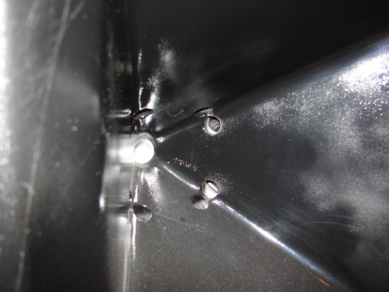
the spike looks like the ports aren't close enough to the throat to cover that high.
3cm from the throat?
/Thomas
What I'm not quite in the clear with is: how do you psysically achieve this? A 5/1 ratio translates to ~(26cm^2)/2 = 2x4cm holes.
Please help me
/Thomas
What i mean is: won't the big mid-holes mess up the high frequency response?
/Thomas
Thomas,What i mean is: won't the big mid-holes mess up the high frequency response?
The exit holes as in post #709 (an 8") had no measurable effect on the output of the Paraline HF, I tried "before and after" holes, the graphs overlayed precisely.
If you plan to use a TPL, the throat will be between the Paraline height and a standard compression driver exit size.
Using a standard 1" throat conical horn the holes may have a slight effect as the percentage of open to closed space would be larger, but by locating them at the corners of the horn and making the exits "sausage shaped" any adverse effect would be minimised.
Also, larger cones put the holes further away from the throat apex, the further away from the throat apex the less effect on HF waves, which are already "formed" in the first 4-5 centimeters of the horn (or driver).
Art
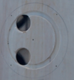
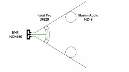
For a unity/synergy horn, I understand the midrange and woofer ports are placed 1/4 of the wave length of the desired crossover points. However, that is a little vague. For example (see attached diagram):
1. Where does one begin measuring from? Is it the diaphragm, acoustic center, or something else?
2. Where does the measurement end? Does one measure to the near side (blue radius), center (orange radius), or far side of the ports (red radius)?
I've made a mold and would like to try using the BMS ND45 crossed over at 1200hz to Faital Pro 3FE20's at 250hz to Illusion Audio ND-8's. I don't know if each crossover point is too low, but I would like to try. If anyone is willing to model these drivers, it would be appreciated. For those who want to know why these drivers, because it is for a car and I already have them. FYI, the drawing is not to scale or proportions.
Thanks!
1. Where does one begin measuring from? Is it the diaphragm, acoustic center, or something else?
2. Where does the measurement end? Does one measure to the near side (blue radius), center (orange radius), or far side of the ports (red radius)?
I've made a mold and would like to try using the BMS ND45 crossed over at 1200hz to Faital Pro 3FE20's at 250hz to Illusion Audio ND-8's. I don't know if each crossover point is too low, but I would like to try. If anyone is willing to model these drivers, it would be appreciated. For those who want to know why these drivers, because it is for a car and I already have them.
FYI, the drawing is not to scale or proportions.Thanks!
Attachments
Last edited:
The local area of expansion (flare rate) dictates how low the mid will play. The cross sectional area dictates how high you will get high frequency loading from the horn. This is a different issue than the 1/2 wave length cancellation notch. The area the mid taps into needs to have a circumference less than or equal to the wave length of highest frequency of interest. For 900Hz you want to tap into the horn where the area is approximately 115cm^2 and 146cm^2 for 800Hz. You have to balance the 1/2 wave length cancellation notch, the local area of expansion, and the area of the tap in point all simultaneously to get a Unity or Synergy horn to work correctly.
Hey John,
IMHO, you and Danley have posted the best information on where to locate the taps for the midranges.
In the years that have passed, many others have built Unity and Synergy horns. I've noticed that many just guess at where to put the midranges holes. In my own experiments, I haven't noticed a dramatic difference between 'eyeballing' the locations, and calculating them.
Due to that, I wrote a spredsheet which compares the local flare rate for various horn angles. It includes the following:
40x40 degrees
An externally hosted image should be here but it was not working when we last tested it.
50x50 degrees
An externally hosted image should be here but it was not working when we last tested it.
60x60 degrees
90x90 degrees (like the Gedlee waveguides)
An externally hosted image should be here but it was not working when we last tested it.
360x0 degrees (like a Paraline)

180x0 degrees (half a Paraline, like my 'Stargate' horn)
Before I post the spreadsheet showing the flare rates of various conical horns, both at the mouth and *in* the horn, we need to define what 'flare rate' is. Here are a few quotes:
http://www.quarter-wave.com/Horns/Horn_Physics.pdf
"the acoustic SPL output produced by transmission lines and consistent exponential horns, leads to the following understanding of why the horn speaker is so efficient. The damping provided by the real part of the acoustic impedance at the horn’s mouth efficiently transfers sound energy into the listening room environment at all frequencies above the lower cut-off frequency fc. Without this constant transfer of energy, a significant portion of the sound energy would be reflected back into the flared geometry producing standing waves at discrete frequencies related to the length and flare rate. These standing waves produce narrow bands of higher SPL in the listening room due to the peaking resonance of the volume velocity at the open end. The consistent horn’s efficient transfer of sound energy into the room produces a more uniform higher SPL output across the frequency spectrum and removes the potential for peaky acoustic output due to axial standing waves associated with a transmission line or compromised horn designs." (Martin King)
How Will A Horn Flare Expansion Rate Increase Affect Response? (Page 1) / FullRangeDriver Forum / Fullrangedriver Forum
"'Faster' flare rate = the larger the mouth must be to get it long enough and the lower the gain with increasing flare rate, ergo for LF/'sub' duty, a 'slower' flare rate is desirable, with hyperbolic for true basshorns and hypex for midbass/bass horns the norm. The pathlength is longer to get to the optimum mouth area, but starting with a smaller throat and slower expansion means it will generate more acoustic power and can be more efficiently folded up.
Expo should be limited to midbass/lower mids, with tractrix, or better yet, conical, for our acute hearing BW and extreme HF.
WRT rapidly flaring the end of the horn, which is analogous to rounding over a vent, it will 'soften' the horn/room pressure transition at the expense of peak gain higher up in its BW. Desirable for a FR driver BLH, usually not for a BW limited compression horn." (GM)
SPL TD-1 and TD-2
"If you read the Unity patent, you can see it is realizing the horn had different flare rates and to tap into the horn where it was appropriate for the frequency. To have the dimensions small enough at the point the different ranges combine so that the sources really combine into a single acoustic source, to have the front to back relationship such that the driver and crossover network’s phase shift are cancelled out. To have the internal dimensions such that multiple sources (for each range) also add coherently (a spacing less than1/3 to ¼ wl typically) The result is ONE horn path, driven at multiple points according to the frequency range."
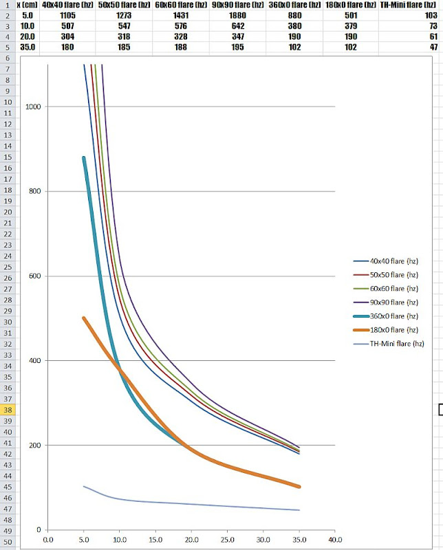
Here's a graph I made, in which I've plotted the local flare rate for seven different horns. In my last post, I mentioned that many are getting good results 'eyeballing' the location of the midrange taps.
I believe the reason for this is that the seven geometries have very similar 'local flare rates' once you get about 10cm (4") down the axis of the horn. YES, this is counter to what I believed even a week ago. Up until a week ago, I thought that narrower horns allowed us to located the midranges further down the horn, and therefore narrower horns were superior. I still believe they're superior, but for a different reason. (I'll get to that in a minute.)
Long story short - I would argue that the midrange taps shouldn't be any closer than 10cm away from the throat. And that any further than 15-20cm will likely lead to a secondary problem, which is a reflection off of the throat.
Here are three hypothetical examples:
example 1: midrange taps located 5cm away from the throat, on a 60x60 conical horn with a square mouth. (IE, like the Lambda Unity Horn or the Danley SH-60.) In this config, we're going to get a notch around 1700hz, due to the reflection off the throat. Local flare rate is 1431hz.
example 2: midrange taps located 10cm away from the throat. Horn size and shape is same as example 1. In this config, we get a notch at 850hz, but our local flare rate is 576hz.
example 3: midrange taps located 20cm away from the throat. Same horn and size shape. Notch is at 425hz, our local flare rate is 328hz.
I'd argue the best option is #2 - with the midrange taps 10cm from the throat. Not much different than this:
Some notes on the data:
1) Every single horn includes the space taken up by the throat. I found that this made a big difference in the flare rate. (IE, this is different than an OS waveguide, where the angle changes gradually at the throat to 'meet up' with the compression driver.)
2) Two of the horns are radial horns; one is a Paraline and one is a 'Stargate.' In the radial horns, the height of the horn is 0.805cm (the same height as luan from Home Depot.)
3) I've included a subwoofer for comparison's sake, the TH-Mini. Note how the subwoofer flare rate is practically constant? And it's flare rate is also very low, as it's designed to reproduce low frequencies.
http://www.quarter-wave.com/Horns/Horn_Physics.pdf
"the acoustic SPL output produced by transmission lines and consistent exponential horns, leads to the following understanding of why the horn speaker is so efficient. The damping provided by the real part of the acoustic impedance at the horn’s mouth efficiently transfers sound energy into the listening room environment at all frequencies above the lower cut-off frequency fc. Without this constant transfer of energy, a significant portion of the sound energy would be reflected back into the flared geometry producing standing waves at discrete frequencies related to the length and flare rate. These standing waves produce narrow bands of higher SPL in the listening room due to the peaking resonance of the volume velocity at the open end. The consistent horn’s efficient transfer of sound energy into the room produces a more uniform higher SPL output across the frequency spectrum and removes the potential for peaky acoustic output due to axial standing waves associated with a transmission line or compromised horn designs." (Martin King)
How Will A Horn Flare Expansion Rate Increase Affect Response? (Page 1) / FullRangeDriver Forum / Fullrangedriver Forum
"'Faster' flare rate = the larger the mouth must be to get it long enough and the lower the gain with increasing flare rate, ergo for LF/'sub' duty, a 'slower' flare rate is desirable, with hyperbolic for true basshorns and hypex for midbass/bass horns the norm. The pathlength is longer to get to the optimum mouth area, but starting with a smaller throat and slower expansion means it will generate more acoustic power and can be more efficiently folded up.
Expo should be limited to midbass/lower mids, with tractrix, or better yet, conical, for our acute hearing BW and extreme HF.
WRT rapidly flaring the end of the horn, which is analogous to rounding over a vent, it will 'soften' the horn/room pressure transition at the expense of peak gain higher up in its BW. Desirable for a FR driver BLH, usually not for a BW limited compression horn." (GM)
SPL TD-1 and TD-2
"If you read the Unity patent, you can see it is realizing the horn had different flare rates and to tap into the horn where it was appropriate for the frequency. To have the dimensions small enough at the point the different ranges combine so that the sources really combine into a single acoustic source, to have the front to back relationship such that the driver and crossover network’s phase shift are cancelled out. To have the internal dimensions such that multiple sources (for each range) also add coherently (a spacing less than1/3 to ¼ wl typically) The result is ONE horn path, driven at multiple points according to the frequency range."
Here's a graph I made, in which I've plotted the local flare rate for seven different horns. In my last post, I mentioned that many are getting good results 'eyeballing' the location of the midrange taps.
I believe the reason for this is that the seven geometries have very similar 'local flare rates' once you get about 10cm (4") down the axis of the horn. YES, this is counter to what I believed even a week ago. Up until a week ago, I thought that narrower horns allowed us to located the midranges further down the horn, and therefore narrower horns were superior. I still believe they're superior, but for a different reason. (I'll get to that in a minute.)
Long story short - I would argue that the midrange taps shouldn't be any closer than 10cm away from the throat. And that any further than 15-20cm will likely lead to a secondary problem, which is a reflection off of the throat.
Here are three hypothetical examples:
example 1: midrange taps located 5cm away from the throat, on a 60x60 conical horn with a square mouth. (IE, like the Lambda Unity Horn or the Danley SH-60.) In this config, we're going to get a notch around 1700hz, due to the reflection off the throat. Local flare rate is 1431hz.
example 2: midrange taps located 10cm away from the throat. Horn size and shape is same as example 1. In this config, we get a notch at 850hz, but our local flare rate is 576hz.
example 3: midrange taps located 20cm away from the throat. Same horn and size shape. Notch is at 425hz, our local flare rate is 328hz.
I'd argue the best option is #2 - with the midrange taps 10cm from the throat. Not much different than this:
Some notes on the data:
1) Every single horn includes the space taken up by the throat. I found that this made a big difference in the flare rate. (IE, this is different than an OS waveguide, where the angle changes gradually at the throat to 'meet up' with the compression driver.)
2) Two of the horns are radial horns; one is a Paraline and one is a 'Stargate.' In the radial horns, the height of the horn is 0.805cm (the same height as luan from Home Depot.)
3) I've included a subwoofer for comparison's sake, the TH-Mini. Note how the subwoofer flare rate is practically constant? And it's flare rate is also very low, as it's designed to reproduce low frequencies.
For a unity/synergy horn, I understand the midrange and woofer ports are placed 1/4 of the wave length of the desired crossover points. However, that is a little vague. For example (see attached diagram):
1. Where does one begin measuring from? Is it the diaphragm, acoustic center, or something else?
2. Where does the measurement end? Does one measure to the near side (blue radius), center (orange radius), or far side of the ports (red radius)?
I've made a mold and would like to try using the BMS ND45 crossed over at 1200hz to Faital Pro 3FE20's at 250hz to Illusion Audio ND-8's. I don't know if each crossover point is too low, but I would like to try. If anyone is willing to model these drivers, it would be appreciated. For those who want to know why these drivers, because it is for a car and I already have them.
Thanks!
In post 721 I posted a graph showing the 'local flare rate' of seven different horn geometries. JLH has a good post here talking about the variables:
http://www.diyaudio.com/forums/mult...e-bandpass-mid-unity-horn-15.html#post2404212
In addition to what JLH said, I would add the following:
1) At every point along the pathlength of the horn, the local flare rate is getting lower in frequency Near the throat the flare rate can change a whole octave if you move just five centimeters.
If you look at my graph, the local flare rate looks like a 'hockey stick' around 10cm. IMHO, that's the region you want to avoid; in the 'hockey stick' region you're mids will interfere with your compression driver. So I'd put them between 10 and 20cm down the horn's pathlength.
2) I would personally avoid getting close to the 20cm mark, because you get a notch in the upper passband of the mid due to a reflection
Due to that, I'd argue the 'sweet spot' is around 10cm. I'd reduce that number by two or three centimeters if you're using midranges smaller than 5".
Last edited:
Hey John,
Performing all the calculations and then making adjustments to the model is how I get all those nice looking Akabak graphs. This works so much better than guessing and building a ton of speakers that don't work.
One of the most common mistakes I see is tapping the mids into a throat area that is too small. This is what leads to the peaking right before the response falls off due to the 1/2 WL cancellation notch. The thing I'm always fighting is the dispersion angles that provide the best loading are not always the best for your room layout.
Agreed. For literally years I thought the reason that Danley was going with narrower and narrower angles was due to the local flare rate.
At this point, I don't think that's the case. Based on some sims I ran, I believe that Danley is going with narrower wall angles because it raises the output level of the compression driver at the xover point. Therefore, narrower wall angles afford a lower xover point, higher power handling, or both.
I have some sims I did with Hornresp that illustrate this and I'll post them soon. The difference is dramatic; going from a 60x60 horn to a 90x90 horn lowers the output of the compression driver by as much as 10dB at the xover point, a massive difference when we're struggling to get the midranges and the compression driver to play nice with each other.
An obvious option would be to use EQ to 'bring up' the compression driver at the xover point, but I think this could wreck the whole thing, as additional boost at the xover is right where we need all the excursion we can get.
- Home
- Loudspeakers
- Multi-Way
- Suitable midrange cone, for bandpass mid in Unity horn.