Keele's paper in which he popularized a 2ndry flare was about a combined exponential & conical horn.
? I guess I'll have to re-read the paper, I remember it being about only conicals (making the point that exponentials aren't sacred or necessary)?
A good reason for the second flare is that it also makes the horn considerabl shorter for the same lower pattern control frequency. Which is nice for WAF, such as it is.
I've never detected a reflection from the beginning of the secondary flare in my synergies, but can easily see it from the end of the horn (which is also the end of the secondary flare). Out where the secondary flare starts, only lower frequencies are in play anymore -- the higher frequencies are already directed by then -- and the shape discontinuity is rather small for the longer wavelengths.
Secondary flares do make the horn considerably more difficult to cut and assemble from plywood, though.
Last edited:
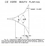
Here is a figure from the famous what's so sacred paper.
You see the initial exponential section which he added to improve low frequency loading. There is only the barest vestige of that in our conical synergies - per Hughes paper if at all.
I noticed he says that the added flare reduces polar lobing/fingering, a benefit I missed in my first post.
You see the initial exponential section which he added to improve low frequency loading. There is only the barest vestige of that in our conical synergies - per Hughes paper if at all.
I noticed he says that the added flare reduces polar lobing/fingering, a benefit I missed in my first post.
Attachments
conical horn directivity plots
Hi Bill:
i think my point about the initial exponential section is besides the point for the reason that you state.
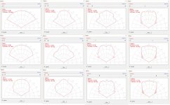
The question as to whether a 2ndry flare is merited was still open in my mind so I did what analysis I could in HornResp. I made a single flare - pure conical - model of my horn so that I could use the HR directivity tool. The polar map that HR produced is frightening and hard to interpret so I did a number of directivity plots over a range of frequencies and consolidated them into the attached jpg.
In the 2nd column, charts for 1 Khz - 1.5 khz, there is some the midband beaming/narrowing that Keele speaks of. My listening position is roughly 19 degrees off axis from the left speaker and 7 degrees off axis from the right, vice versa for my wife. I might be able to EQ this region to +/- 2 db at best. Probably not near as good as you are getting from the SEOS15 in the Small Syns. I wonder how much of a secondary flare it would take to correct that. HR won't tell me; once I add a 2ndry flare to the model the directivity tool no longer works.
And its not really a model of my horn; its a model of an axisymmetric horn with the same mouth area. Furthermore, mine is a corner horn. I hope(d) the horn is close enough to the walls that the walls reduce this narrowing. Given that its occurring at 1500 Hz and the distance from horm wall to room wall is 3.5", 1/4 lambda at 966 Hz, I don't think so or at least not very much. The primary benefit of the corner will be confining the Horizontal radiation at lower frequencies. OTOH, my horn is 90x45 and the midband narrowing in the horizontal plane might be occurring at a substantially lower frequencies where the proximity of the walls would help. I should repeat the simulation with a model having a mouth diameter equal to the width of my horn.
The right two columns of charts exhibit what could be called polar lobing, again as described by Keele. It looks small enough to me to not be worrisome. But the midband narrowing, now that I have some idea where it occurs, could well be worth addressing. I won't know till I get everything optimized in room and see how flat I can EQ the frequency response across my couch.
Hi Bill:
i think my point about the initial exponential section is besides the point for the reason that you state.
The question as to whether a 2ndry flare is merited was still open in my mind so I did what analysis I could in HornResp. I made a single flare - pure conical - model of my horn so that I could use the HR directivity tool. The polar map that HR produced is frightening and hard to interpret so I did a number of directivity plots over a range of frequencies and consolidated them into the attached jpg.
In the 2nd column, charts for 1 Khz - 1.5 khz, there is some the midband beaming/narrowing that Keele speaks of. My listening position is roughly 19 degrees off axis from the left speaker and 7 degrees off axis from the right, vice versa for my wife. I might be able to EQ this region to +/- 2 db at best. Probably not near as good as you are getting from the SEOS15 in the Small Syns. I wonder how much of a secondary flare it would take to correct that. HR won't tell me; once I add a 2ndry flare to the model the directivity tool no longer works.
And its not really a model of my horn; its a model of an axisymmetric horn with the same mouth area. Furthermore, mine is a corner horn. I hope(d) the horn is close enough to the walls that the walls reduce this narrowing. Given that its occurring at 1500 Hz and the distance from horm wall to room wall is 3.5", 1/4 lambda at 966 Hz, I don't think so or at least not very much. The primary benefit of the corner will be confining the Horizontal radiation at lower frequencies. OTOH, my horn is 90x45 and the midband narrowing in the horizontal plane might be occurring at a substantially lower frequencies where the proximity of the walls would help. I should repeat the simulation with a model having a mouth diameter equal to the width of my horn.
The right two columns of charts exhibit what could be called polar lobing, again as described by Keele. It looks small enough to me to not be worrisome. But the midband narrowing, now that I have some idea where it occurs, could well be worth addressing. I won't know till I get everything optimized in room and see how flat I can EQ the frequency response across my couch.
Attachments
Is there any more options to extend the freq response of my mid-range drivers?
Here is what I have done so far:
Speakers as close to CD as possible.
Extend Frustrums (pictured below)
Added Phase/filler plugs (like picture attached below)
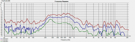
Here is the measurements with the added filler plugs:
Red trace is 1 meter from horn
Blue trace is 6 inches from horn
Green is without the filler plugs
The mid-range plots are very smooth right now with the phase/filler plugs. They helped reduce the hump @ 250hz and smooth out the 800-1200hz area. Without crossover applied it is a perfect 12db rolloff on the top and bottom. However, it is still just a bit low in top end freq response.
I see that Jmorken used this driver too here:https://www.google.com/url?sa=t&rct=j&q=&esrc=s&source=web&cd=1&cad=rja&uact=8&ved=0ahUKEwjRzIfbuKfNAhXESCYKHW7TAHgQFggcMAA&url=http%3A%2F%2Fwww.diyaudio.com%2Fforums%2Fmulti-way%2F195955-unity-horn-budget-drivers-active-x-over.html&usg=AFQjCNGMwqKZ7FuLuf0c-cZiSz48U3Jiuw
I based my build of this thread when I first started but now I see that he never really got this mid-range to extend much past the same 800-1100 12db rolloff I am getting.
Here is what I have done so far:
Speakers as close to CD as possible.
Extend Frustrums (pictured below)
Added Phase/filler plugs (like picture attached below)
Here is the measurements with the added filler plugs:
Red trace is 1 meter from horn
Blue trace is 6 inches from horn
Green is without the filler plugs
The mid-range plots are very smooth right now with the phase/filler plugs. They helped reduce the hump @ 250hz and smooth out the 800-1200hz area. Without crossover applied it is a perfect 12db rolloff on the top and bottom. However, it is still just a bit low in top end freq response.
I see that Jmorken used this driver too here:https://www.google.com/url?sa=t&rct=j&q=&esrc=s&source=web&cd=1&cad=rja&uact=8&ved=0ahUKEwjRzIfbuKfNAhXESCYKHW7TAHgQFggcMAA&url=http%3A%2F%2Fwww.diyaudio.com%2Fforums%2Fmulti-way%2F195955-unity-horn-budget-drivers-active-x-over.html&usg=AFQjCNGMwqKZ7FuLuf0c-cZiSz48U3Jiuw
I based my build of this thread when I first started but now I see that he never really got this mid-range to extend much past the same 800-1100 12db rolloff I am getting.
Attachments

THANK YOU for taking the time to work on the question of the 2nd flare.
Its always been an interesting and significant question for me as well. I may have more to say on it but I will do that in my own thread.
As to your mids: the only thing you can do is try different size mid port holes and moving them closer to the apex. I can't see a reflection null in your frequency response, which is not uncommon, but there usually is a phase discontinuity there. If you see a phase jump around 1 Khz, it's a sign your port holes need to move closer to the apex. I see they are centered in the frustrum holes. If you moved them to the inside edges of the frustrum holes, the half inch or so you might gain could be significant.
When the reflection from the apex isn't limiting the upper end, the bandpass chamber and port tuning come into play. Minimizing the air volume under the cone is of course the first thing to do. In HR, you can see huge differences in response by playing with hole size at constant port length, or port length at constant hole size (or play with both at once, if you want to confuse yourself). So if you do try moving the holes, I would suggest starting with a small hole and then gradually enlarging it until satisfied with the response.
I am afraid I have squeezed out everything I can from these budget mids and this current horn build. I would need to swap either of three things.
1. The cheap mids, but then the ports/location/etc would not match new drivers.
2. The Horn itself. Easy to build again but this build will do what I want it to do. Play loud and clean & sound good
3. The CD, not doing that now. However I think the DNA360 might get a bit lower and be close enough to keep everything else. Keep my eye out for the swap meet.
"As to your mids: the only thing you can do is try different size mid port holes and moving them closer to the apex."
The ports are as close to the Apex of the driver as I can. The picture I provided will show it better. They are currently 4mm long. I am not really willing to try to shave off much more at this point.
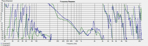
"I can't see a reflection null in your frequency response, which is not uncommon, but there usually is a phase discontinuity there. If you see a phase jump around 1 Khz, it's a sign your port holes need to move closer to the apex."
Here is the phase of a speaker with and without the phase/filler plug. There was a bump around 1K in the driver without the phase/filler plug (GREEN) and now the driver with the phase/filler plug that phase bump is shifted up to 2K (BLUE)
There is very little room under the mid to minimize. There is 1/8th (3.17mm?) clearance between the dust cap and phase plug. I could in theory fill more, but would rather play it safe.
Some pictures:
1. The cheap mids, but then the ports/location/etc would not match new drivers.
2. The Horn itself. Easy to build again but this build will do what I want it to do. Play loud and clean & sound good
3. The CD, not doing that now. However I think the DNA360 might get a bit lower and be close enough to keep everything else. Keep my eye out for the swap meet.
"As to your mids: the only thing you can do is try different size mid port holes and moving them closer to the apex."
The ports are as close to the Apex of the driver as I can. The picture I provided will show it better. They are currently 4mm long. I am not really willing to try to shave off much more at this point.
"I can't see a reflection null in your frequency response, which is not uncommon, but there usually is a phase discontinuity there. If you see a phase jump around 1 Khz, it's a sign your port holes need to move closer to the apex."
Here is the phase of a speaker with and without the phase/filler plug. There was a bump around 1K in the driver without the phase/filler plug (GREEN) and now the driver with the phase/filler plug that phase bump is shifted up to 2K (BLUE)
There is very little room under the mid to minimize. There is 1/8th (3.17mm?) clearance between the dust cap and phase plug. I could in theory fill more, but would rather play it safe.
Some pictures:
Attachments
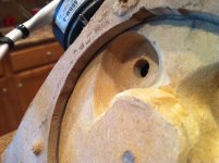
Based on the pictures my guess is you've left too much clearance for suspension travel and, as a result, still have too much air trapped under the cone.
I had the same problem in mine so I filled back in what I had dug out, except for tapered/frustrum portion, with joint compound (temporarily) and it worked. My mids had a half-roll surround so all I needed for suspension travel was a 1/4" wide trench overlapping that half roll. Its different for an accordion surround but you can be reasonably confident that there is no movement at the outer edge and maximum movement where it transitions from suspension to cone. Consequently some kind of tapering can be done to minimize the free air volume but the main thing is not digging any deeper than necessary.
I doubt that Xmax on those drivers is more than 2mm or that you need more than 2mm to meet your SPL goal. I've heard it recommended that Xmech be allowed for but I wouldn't go quite so far if doing so limited the high end too much.
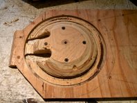
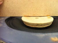
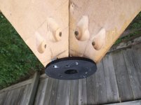
That speaker is the ugly duckling. The horn was a bit off on this side and required a spacer to keep from pushing into the other drivers frame. Instead of chewing the metal frame up I added a spacer ring. The other drivers have less space in the chamber. I only pulled this driver to show the proximity of the ports to drivers edge.
HipCheck,
One thing that MIGHT improve the high end (but no guarantees of course) is if you opened the path from the center of the cone to the apertures a little better. As shown, the pressure from the cone has to travel over a wide range of distances around things to get to the holes, and forcing multiple paths can result in cancellations and loss at higher frequencies. You do want to keep the the trapped air volume down, but still maintain a consistent path (ideal a path the same distance from all points on the cone to the holes, though that's obviously not going to happen) -- but I think it could be better than shown. If it were me, I'd fill in around the outer part of the cone area, but open up the two gouges toward the center.
One thing that MIGHT improve the high end (but no guarantees of course) is if you opened the path from the center of the cone to the apertures a little better. As shown, the pressure from the cone has to travel over a wide range of distances around things to get to the holes, and forcing multiple paths can result in cancellations and loss at higher frequencies. You do want to keep the the trapped air volume down, but still maintain a consistent path (ideal a path the same distance from all points on the cone to the holes, though that's obviously not going to happen) -- but I think it could be better than shown. If it were me, I'd fill in around the outer part of the cone area, but open up the two gouges toward the center.

I just added the filler plug to reduce volume this week. It was very roughly shaped (hobby knife, lol) I plan to smooth it out with my Dremel tomorrow morning. It did smooth out the freq response.
Here are some pictures.
#1 how everything was before the filler plug was added. Frustrums were scooped out toward the center like you mentioned (will shape the plug better and report back) this is what resulted in the Green trace below.
#2 The green trace is before the filler plug, Blue is taken from the same position (scaled up to allow easy comparison) after the filler plug was added.
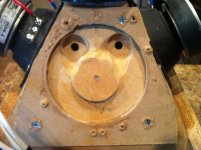
Yes I was asked by my son to turn this into a pigs face before I put the driver back on. These are big and ugly on the inside, so I guess we can call these the "BIG PIGS"
Thanks for all the feedback guys
Here are some pictures.
#1 how everything was before the filler plug was added. Frustrums were scooped out toward the center like you mentioned (will shape the plug better and report back) this is what resulted in the Green trace below.
#2 The green trace is before the filler plug, Blue is taken from the same position (scaled up to allow easy comparison) after the filler plug was added.
Yes I was asked by my son to turn this into a pigs face before I put the driver back on. These are big and ugly on the inside, so I guess we can call these the "BIG PIGS"
Thanks for all the feedback guys
Attachments

I want to throw birds at it.
With regards to mouth termination (is it fair to say this is already 18" (25" diagonal) or so across?) you could also try a radius. There is some guesswork here, the lower frequency pattern control extension and smoothness, lower frequency axial mouth reflection and higher frequency diffraction will be vying for attention if you can't afford much extra width, but where you can the solution becomes clearer.
With regards to mouth termination (is it fair to say this is already 18" (25" diagonal) or so across?) you could also try a radius. There is some guesswork here, the lower frequency pattern control extension and smoothness, lower frequency axial mouth reflection and higher frequency diffraction will be vying for attention if you can't afford much extra width, but where you can the solution becomes clearer.
Attachments

Found a 6.5" sealed mid driver that could be a good candidate. Details are here:
ÉîÛÚÊа²µÄÒôÏìÉ豸ÓÐÏÞ¹«Ë¾
ÉîÛÚÊа²µÄÒôÏìÉ豸ÓÐÏÞ¹«Ë¾
Look like these places will order them:
Celestion TF0410MR 4inch Midrange Speaker 25.00
Celestion Truvox 0410 MR (8Ohm)
An externally hosted image should be here but it was not working when we last tested it.
Parts Express is now stocking a driver that seems to be a potential replacement for the hard-to-get Celestion TF0401MR. Seems like this might enable us to make SH50 clones (finally.) The BMS tweeter is available from US Speaker and the B&C woofers are available just about everywhere, but those Celestion midranges have been hard to come by.
The 'catch' is that you'd have to make a back chamber for it.
Here's the T/S:
fs = 95hz
qes = 0.35
2 x (FS/QES) = 543hz
diameter = 4.75"
At $480 for a set of eight, it's more expensive than the Celestion or the Misco, but much easier to buy.
Eminence PRO 5W-8 5" Cast Frame Woofer
Thank you John,
What could be a good F3 of those drivers according to you ?
Now, the Hunt to the best unit for the Apex is open !
!
Hope some good news from Baswlo to come when he will be healed for saying us more about the Tymphany compression driver in his new synergy speaker when it will be finished...
What could be a good F3 of those drivers according to you ?
Now, the Hunt to the best unit for the Apex is open
!Hope some good news from Baswlo to come when he will be healed for saying us more about the Tymphany compression driver in his new synergy speaker when it will be finished...
If you're going to make a back chamber, the FaitalPro 3FE22 is less expensive and works very well on a horn. I originally was using them in the SmallSyns, but changed to the Celestion for simpler assembly -- I think Erich at DIYSoundgroup can get them, and may start carrying them if I can get him to offer a kit.
Simplier is better with no skilled people as I am
A big problem with the diysoundgroup is it's very expensive for europeans to get the whole kit (heavy drivers) because of the taxes on the shipment costs and customes taxes (the same about the whole kits of diys parts shops). For Instance I think the Tempest from Jeff B. can cost for us the twice of the US fees.
A Seos horn is light and it's ok, but coils and PA drivers are an other story ! Plus many of these european PA brands are not expensive for us when sold locally !
For a licencing we should need a Linkwitz licencing system... or follow your thread if you make public the sizes and filter values (be it active/passive)
Hope your flue is ok and you can get a rest to cure it totally.
A big problem with the diysoundgroup is it's very expensive for europeans to get the whole kit (heavy drivers) because of the taxes on the shipment costs and customes taxes (the same about the whole kits of diys parts shops). For Instance I think the Tempest from Jeff B. can cost for us the twice of the US fees.
A Seos horn is light and it's ok, but coils and PA drivers are an other story
! Plus many of these european PA brands are not expensive for us when sold locally !For a licencing we should need a Linkwitz licencing system... or follow your thread if you make public the sizes and filter values (be it active/passive)
Hope your flue is ok and you can get a rest to cure it totally.
Thanks Eldam. Flu is over now, I'm just catching up on household projects before getting back to the SmallSyns.
There won't be any licensing on them, I plan to put the whole design, along with building details online. -- As soon as I settle on just what that design will be of course (it's changed a number of times, now after I thought I was nearly done) -- I hope when I test the newest crossover it can be finished up. (Parts are in, along with parts to make a ported version).
Putting a back chamber on an open-backed driver isn't really very hard if you have the right size cardboard or pvc tubes and are good with cutting and cluing hardboard, but it is quite a few extra steps to do, and it might be difficult to assure that each build is similar enough to the original. On the 3FE22, offset loaded onto a SEOS15, the back volume has to be pretty small so even a little variation in construction might cause a lot of change, percentage-wise.
- Home
- Loudspeakers
- Multi-Way
- Suitable midrange cone, for bandpass mid in Unity horn.