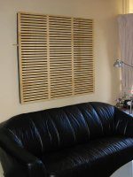
I've built myself some acoustic absorbers. They help to control the sound being reflected off the rear wall behind the listening position.
The overall dimesions are 1m high, 1.2m wide and 160mm deep. It's a broadband design and is effective down to about 150Hz becoming acoustically transparent below 100Hz.
It looks very striking and suits a modern decor. It also works very well! For anyone that has a similar problem where they are forced to have their listening position close to the rear wall, an absorber of this type is very effective.
There's a lot more information on a new web page devoted to it. Check it out! http://www.aeronet.com.au/Aeropanel Absorber.htm
Cheers, Ralph.
Attachments
A very nice blending of form and function - they would go nicely in most rooms I think - almost looks like a wall hanging, or a very large ventilation outlet! 
How did you construct the wood panel - did you just route the slits in it? I'm thinking one could be very creative with something like this - maybe cover it wil perforated metal gratings, etc., which are available in lots of home decor-type finishes.
A lot of people probably would not know that these were part of a home audio system, until they asked.
Ralph,
I very much like the design it reminds me of stuff done by "Recording Architecture". http://www.aaa-design.com/gallery/index.htm
It looks like it is a helmholtz slot absorber. I have to say though, I my calculations don't agree it will work down to 100Hz. More like 400Hz at most, bar a little bit passing straight through the panel and seeping round the side.
What is the width of the slots and the width of the gaps between the slots?
richie00boy said:Looks good. I might have a bash someday as I find a lack of focus in sat in my sofa by the wall but it sounds good if I move forward a bit.
What precisely is acoustic foam? Is bonded acetate fibre (BAF wadding) any good?
This is the exact problem that I'm having, I posted a thread about this a week ago, toeing in the speakers helped with the focus a bit more. But, I think I will try this panel as well.
Again, what exactly is the acoustic foam? Is it similar to eggcrate foam or those studio panel foam?
Hi sdclc,
Thanks for the compliment! The slots are simply routed with a CNC router. There's lots of creative possibilities available depending on your decor. I liked this approach for it's simplicity and the wood finish. The woodgrain looks a lot better in real life. The photo doesn't do the wood justice.
Hi Tenson,
Thanks for the link to the studio pictures. There's lots of cool ideas there!
It does look a bit like a Helmholtz slot resonator, but it's not, because it has no enclosure behind the panel. In order to resonate it would need to have an enclosed volume of air. My panel is just acoustic foam with a decorative cover.
I've made my estimations of the low frequency cut-off from manufacturer's data. I fully expect the panel to operate down to about 150Hz. Unfortunately I don't have a reverberation chamber to actually measure the performance of the panel! There's some more info about the expected performance on the web page. http://www.aeronet.com.au/Aeropanel Absorber.htm
There's 20mm of material between the slots BTW.
Hi Richie,
Sounds like you have exactly the same problem as I did. I'm sure you will find a big improvement in the imaging if you tame the reflection from the rear wall.
Acoustic foam is open-cell polyeurethane foam -ie the air bubbles in the material are open to one another. In a thin sheet it's possible to blow air through the material. Conversely, the stuff that goes into pillows is a closed-cell foam where each air bubble is distinct. It's more difficult to manufacture open-cell foam and it's not as common, so it's relatively expensive. The closed-cell foam is too resilient and doesn't dissipate sound energy very well, so it's not suitable as an acoustic absorber.
BAF wadding might be suitable if it was highly compacted and made thick enough (You'd probably need to squash half metre of BAF down to 50mm to get it dense enough). Fibreglass wool would be much better though. Unfortunately the glass fibres are a health hazard, hence the choice of foam.
Hi asqlkev,
Definitely experiment with something to quash the rear wall reflection. I simply used the bare foam to experiment with initially. Once you're confident that it helps, you can add a decorative cover later on. As I mentioned in the web page, the mix of absorbant material behind a partially reflective cover gives the best results. Just foam on it's own, makes the rear wall sound far too dead. Don't forget that it also needs to be as thick as possible to be absorbant to low frequencies.
Cheers, Ralph
Thanks a lot. Do you have any recommended brands or sources for this foam? Is the size of the slots anything to do with the frequency or is it just the thickness of the foam? If it's just the thickness is your 150Hz just taken from manufacturers data?
I was thinking about mounting a canvas artwork over some foam - would this work as well?
I was thinking about mounting a canvas artwork over some foam - would this work as well?
Hi Richie,
On this side of the world I used a foam manufactured by a New Zealand company called Latimer. I suggest you try google for some sources in the UK.
I just had a look and came up with http://www.studiospares.com/pl_65_65120_ACOUSTICS_SOUND INSULATION.htm & http://www.foamtechniques.co.uk/acoustic.htm
Studiospares seem to sell precut tiles and other specialised pieces. That's ok, but the tiles tend to be much more expensive. I'd try someone like Foam Techniques. You can probably buy 50mm acoustic foam by the metre from them. For an idea on price, a linear metre of 50mm foam costs about A$80 here.
The slots have little to do with the low frequency performance, it's the thickness that counts. I've estimated the low frequency performance from manufacture's data based on thinner materials. I suggest you have a look at my web page for more detail about this. http://www.aeronet.com.au/Aeropanel Absorber.htm
Canvas artwork is ok as long as it's a partially open weave and not fully covered with paint or other solid material. The requirement is to have enough open area for the sound to pass through, but not be fully absorbant. So the canvas idea will probably still need to have a partly solid material underneath it.
Cheers, Ralph
ralphs99 said:Canvas artwork is ok as long as it's a partially open weave and not fully covered with paint or other solid material. The requirement is to have enough open area for the sound to pass through, but not be fully absorbant. So the canvas idea will probably still need to have a partly solid material underneath it.
Thanks again. I'm not sure what you mean by that bit though, particularly about having something solid underneath. I was thinking of putting a canvas on a frame over some foam.
Ahh okay Ralph, I see looking at the picture it is not 'boxed in'.
I would suggest that experimenting with the thickness of the panel on the front would get some good results. Using a thinner panel you can make it reflective at high frequencies and less at low frequencies. In most cases you want as much absorption as possible from about 200Hz downwards to get really tight bass.
I might try a panel 3mm thick rather than 9mm.
Also, apart from the reflected sound, the sound that goes through the slots will be diffused on its way out. The shape of the slots will alter that radiation pattern. I would suggest having circles so you get a 360degree radiation pattern, or putting the slots vertically so sound is radiated in a 180degree patters across the horizontal plane of the room where there are more objects to help diffuse it further.
I'd suggest using water based paint that soaks into the fabric or even ink. You want to avoid a paint that will 'gunk' up the fabric and block sound passing through.
Underneath you then might want a hard surface with lots of holes or slots in to stop the room being too dead from all the absorption. What about those sheets you get for radiator covers with all the patterns in them?
I would suggest that experimenting with the thickness of the panel on the front would get some good results. Using a thinner panel you can make it reflective at high frequencies and less at low frequencies. In most cases you want as much absorption as possible from about 200Hz downwards to get really tight bass.
I might try a panel 3mm thick rather than 9mm.
Also, apart from the reflected sound, the sound that goes through the slots will be diffused on its way out. The shape of the slots will alter that radiation pattern. I would suggest having circles so you get a 360degree radiation pattern, or putting the slots vertically so sound is radiated in a 180degree patters across the horizontal plane of the room where there are more objects to help diffuse it further.
richie00boy said:
Thanks again. I'm not sure what you mean by that bit though, particularly about having something solid underneath. I was thinking of putting a canvas on a frame over some foam.
I'd suggest using water based paint that soaks into the fabric or even ink. You want to avoid a paint that will 'gunk' up the fabric and block sound passing through.
Underneath you then might want a hard surface with lots of holes or slots in to stop the room being too dead from all the absorption. What about those sheets you get for radiator covers with all the patterns in them?
Hi Tenson,
I don't think the thickness of the panel is going to make much difference to the amount of absorption.
The slots are 10mm wide and 9mm deep. The wavelengths to be significantly affected by such dimesions would be of the order of 40mm or less. 40mm or less represent wavelengths of 9kHz or more.
I'm not too worried about what happens that high up. The concern that prompted construction of the panels was imaging, and this is primarily a mid range issue. The ultra high frequencies just add a sense of space and have little to do with imaging.
Another thing to consider if you want significantlly thinner panels is the ability of the panel material to retain it's structural integrity after being routed. I found that the plywood was seriously weakened with the large open area I used.
Cheers, Ralph
ralphs99 said:Hi Tenson,
I don't think the thickness of the panel is going to make much difference to the amount of absorption.
The slots are 10mm wide and 9mm deep. The wavelengths to be significantly affected by such dimesions would be of the order of 40mm or less. 40mm or less represent wavelengths of 9kHz or more.
I'm not too worried about what happens that high up. The concern that prompted construction of the panels was imaging, and this is primarily a mid range issue. The ultra high frequencies just add a sense of space and have little to do with imaging.
Another thing to consider if you want significantlly thinner panels is the ability of the panel material to retain it's structural integrity after being routed. I found that the plywood was seriously weakened with the large open area I used.
Cheers, Ralph
On the contrary, locational information is in the high frequencies. The first thing our mind does is pinpoint the location of a sound in the horizontal plane from the transients.
Anyway my aim is not to absorb lots more high frequencies as you said you don’t want a dead sounding room. My aim in making the panel thinner is to simply shift that 9KHz point upwards a bit to more like 13-15KHz which would also make it absorb more in the midrange. You must remember waves are not an exact science, so the panel will still be having an effect at 3KHz or so. The size of the space between the slots also count towards the high frequency cut-off point, not just the size of the gaps.
I don't think it would make much difference but if building from new I'd go for a slightly thinner panel that’s all.
A curved panel would also help and maybe even some dowel rods down its length to help scatter high frequencies and also add strength to a thinner panel.
You may like to read up on binary amplitude diffusers, but it will keep your router very busy
Tenson said:
You may like to read up on binary amplitude diffusers, but it will keep your router very busy
More details needed please Simon!
Can you provide links to pictures and thorough explainations plus your own take on what should be done?
As I understand its a 2d primitive root diffuser mixed with low frequency absorbtion? Is it a jack of all trades?
This is the info I know exists on the web and should be enough to build your own http://www.rpginc.com/research/6i2.htm
It is indeed a jack of all trades and master of none. The increase in low frequency absorption is not really that much. It is probably mainly caused by the panel resonating and being damped by touching the foam behind. Certainly not a substitute for a bass trap but it is a nice side effect, and one of the reasons to use a thin and un-braced panel. I don’t want to give too much away about clever designs though
There is a lot more info on the design of them in the book I mentioned before called 'Acoustic Absorbers and Diffusers: Theory, Design and Application' but it has been some time since I got a look at that book. I think I will borrow it again. To be honest my maths is not really up to the level required to fully understand all that is in the book but it still has some very good stuff in there.
Hi Tenson,
Thanks for the link to the amplitude diffusors. They look very interesting for space-challanged listening rooms.
In regard to the discussion about slot size, I think you are confusing my intentions. I agree that the ear is capable of resolving directional information using clues in the 5kHz+ range although the ultra-high frequencies are of much less importance than lower frequencies. However, I am aiming at improved imaging when listening to loudspeakers. Imaging isn't affected by very high frequencies in reproduced sound.
I think it's worth looking at the issues surrounding imaging is a bit more detail just becuase it's interesting and enlightening. Let's begin with the ear's ability to localise sound:
The main mechanisms the ear uses to determine the direction of a sound are the inter-aural time difference (ITD) and the inter-aural level difference (ILD).
The ITD is useful for low frequencies where the wavelength is long and much greater than the path length between ears. The ear uses the ITD for estimating the phase difference between ears for an incident sound wave. The effect is most pronounced below about 1kHz although the effect is still useful for higher frequencies if modulated by a lower tone.
The ILD takes over at higher frequencies, including the region where the ear is most sensitive around 3kHz. The physical size of the head causes shadowing of incident sound waves allowing the brain to determine the direction of a sound by measuring the level difference between the two ears. The effect is still strong to the limit of aubility, however the ear's sensitivity around 3kHz make this the region where the brain makes best use of the effect. In other words there is no additional useful information present at very high frequencies for the ILD. The only place an ILD clue at 10kHz could be useful is for artifical tones. Real sounds have fundamentals very much lower than this.
The anatomical transfer function is another more subtle mechanism to assisting the ear to localising a sound source. It helps in placing a sound source front-to-back and overhead. It's effectiveness is in the very high frequencies above 5kHz.
All of the above describes the mechansisms the ear uses to identify the direction of an incident sound. But this is different to imaging. Imaging is art of preserving localisation cues through a reproduction chain. The aim being to fool the ear into thinking that the real performance is present.
With stereo there are two speakers, and imaging and hence localisation can only occur laterally. There is no genuine front-to-back information, other than there's nothing up back. There is no vertical information present either as both speakers are in the same veritcal plane. The illusion of front-to-back information being present can only be achieved by preserving some of the directional information present in the orinal performance, but there's still only two laterally placed speakers. The ear can therefore only use the ILD and ITD and not the anatomical transfer function.
However there is an additional trick available to a stereo speaker setup to fool the ear, the precedence effect. Normally a sound source has a unique location in space. With a pair of stereo speakers the realtive amplitude difference between the speakers can influence the apparant location of the sound. This a highly artifical effect. It has no analogue in real life. The pan-pot is the electrical tool used to create the illusion. It is primitave in that it destroys the phase realtionships that the stereo reproduction chain is capable of providing. In order to get a realistic illusion of the original performance it is essential that as much of the phase information present in the original performance be retained.
The best way to capture the phase information is with a co-incident microphone pair. The two diaphragms are placed directly on top of one another in the vertical plane with as small a spacing as possible. Given that the microphone capsule will typically have a diameter of about 25mm, the centre-to-centre spacing of the diapragms will be at best 25mm. 25mm starts to become of little importance to wavelengths of the order of around 100mm or more. 100mm represents a frequency around 3.5kHz. So the stereo reproduction chain is limited by the microphone, the very first step in the reproduction chain, to providing imaging information to the listener only below this frequency. Above this frequency the phase information is random and confused and the ear cannot use it for directional cues.
This is why I believe that that slots or holes even as large as 25mm or more in an absorber or diffusor will not adversely affect the phase information available in a recording and hence will not adversely affect imaging.
Sorry if I'm being pedantic, but I do like being able to justify my design decisions!
Cheers, Ralph
Are you sure the top layer needs to be porous? A thin foil or thin layer of alkyde or acrylic paint should not hurt, because as long as its mass density is low, the sound wave will pass right through it (and a couple of % reflectivity might actually be desirable).
Also, for effectivity of any absorbing material, placement is probably more important than raw thickness. A 3 cm layer placed 5 cm away from the wall will be almost as effective as 8 cm of solid absorber right on the wall.
The key here is that those absorbers can attnuate only the velocity wave, not the pressure wave. The solid wall will give you a maximum of pressure at the wall, hence the first maximum of velocity will be a quarter wave away from the wall.
Hi Capslock,
Yes, you're correct, paint would only have a significant effect at high frequencies where it would tend to be reflective rather absorptive. I guess it depends on the effect you're after, the balance in absorption between lower and higher frequencies.
In my case I found the most pleasing combination of acoustics and aesthetics to be the design shown. But there's plenty of other options depending on your particular acoustic problem.
Cheers, Ralph
- Status
- This old topic is closed. If you want to reopen this topic, contact a moderator using the "Report Post" button.
- Home
- Loudspeakers
- Multi-Way
- Aeropanel acoustic absorber