Hi guy's have done a search and didnt uncover what im really looking for. If you know of a thread or two i have missed, please, dont hesitate to let me know ")
I have seen the current group buy for the very nice active XO boards. But i noticed they are designed to be a set value board. Does anyone here use an active xo that is adjustable/programmable?
Basically i want to build an active crossover which i can use on different speaker systems at different times. Are the adjustable active XO's not as good sounding as a set value XO?
Any help is greatly appreciated.
Thanks for your time!
Scribble
The roll-off frequency for an active filter is set by resistor and capacitor values. Adjustable active XOs use fixed capacitor values and variable resistors to set the frequency. The basic circuits and formulas can be found in this wonderful archive:
http://linkwitzlab.com/filters.htm#2
For a filter with 12dB/oct roll-off, you will need two pots ganged together on a shaft so that they track. Four pots are needed for 24dB/oct. The problem is that matching between the pots is rarely better than 20%, whereas active filters really need 5% matching and ideally 1%. A filter with resistors that are 20% off will work but the slopes won’t be ideal.
Another problem with the high-pass Linkwitz-Riley 24dB/oct filter is that the resistors need to have a ratio of 2:1, ie one variable resistor needs to be twice the value of the other. Low pass have the capacitors in a 2:1 ratio so do not suffer from this problem.
If you really want to make adjustments, the best method would be to have, say, three sets of fixed 1% value resistors of whatever values to give you different frequencies and switch between them. Either that or go digital!
Nice one,
David.
http://www.marchandelec.com/xm1.html these boards are real easy to change resistors values on.
daatkins said:For a filter with 12dB/oct roll-off, you will need two pots ganged together on a shaft so that they track. Four pots are needed for 24dB/oct. The problem is that matching between the pots is rarely better than 20%, whereas active filters really need 5% matching and ideally 1%. A filter with resistors that are 20% off will work but the slopes won’t be ideal.
Another problem with the high-pass Linkwitz-Riley 24dB/oct filter is that the resistors need to have a ratio of 2:1, ie one variable resistor needs to be twice the value of the other. Low pass have the capacitors in a 2:1 ratio so do not suffer from this problem.
You could use an individual pot for each resistor. Standard adjustables use ganged pots with their associated troubles. I have a JBL crossover with a 4 gang pot (!) for frequency setting.
There is nothing written in stone that says all sections of a filter must have the same corner frequency. Having different corners will allow you to take care of baffle step and driver response irregularities. You could measure and make sure all were set at the same value if you can accept not changing on the fly.
The group buy board uses the Sallen-Key equal component value topology. The 2X situation David mentioned is true for L-R filters using S-K Unity Gain topology, but in this case the resistors and caps can be equal in high and low pass sections. The Q is controlled by feedback resistors.
One possible solution for step adjustable crossovers would be to use pin sockets at the frequency setting resistor positions and plug in either a bare resistor or a resistor on a small piece of perfboard with mating pins (allowing you to annotate what frequency the resistor sets). Not as neat as the Marchand module, but workable. (I've heard that the low range Marchand filters are State variable topology, which may not sound as good as Sallen-Key or MFB.)
If you go with the group buy boards consider getting a set each for low, mid and high ranges, since resistor values can get unwieldy with one capacitor over a broad range. High resistor values and the filter could be noisy and too low and the op amps might have trouble driving the following stage.
Another option would be to get a few sets of boards, since they are relatively inexpensive. With connectors mounted appropriately you could swap out the XO guts in one enclosure/power supply for multiple speakers fairly easily.
Rotary switches would work, but they either offer limited adjustability or great cost.
Hope this helps your decision process.
Hi Scribble:
Have you seen this one?
http://www.passdiy.com/gallery/hi-lo-xover-p1.htm
The following is the compact version of the above:
http://www.moxtone.com/mox.htm
Both are adjustable. They can be modified so that the front panel knobs also include the Q factor, slope and frequency controls but, mind you, this would complicate things to a considerable degree, both implementation- and money-wise.
Regards,
Milan
Hi,
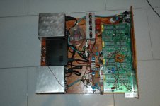
I've been using the MOX for quite some time now, and as Moamps said while possible it is not really practical to wire all settings to pots / front panel knobs. Also, in my case (a 3-way with additional patches for various notch and shelving filters) the whole thing is a spaghetti forest. The attached pic is *one* channel btw...
Seriously it is much easier to buy a set of the current group buy pcb's for each speaker you have. And, maybe one additional set with pin sockets. I use this method for my veroboard notch filters patched into the MOX ...
Attachments
Hi guys,
Thanks for all your responses they have been very helpful. I see you points about adjustable crossovers . I quite like the idea of a module system, one enclosure and power supply system with swappable boards.
Bob, im a bit confused with what you say here
Would you be able to elaborate a bit more for me please? im not fully understanding why i would use a seperate board for each range
Also i noticed on bob's page it talks about using a MOX for prototyping before actually settling on a final design and implementing it onto the group buy boards. Is this what most of you guy's do? as you can see im an active XO n00b
Thanks for your time!
Scribble
Thanks for all your responses they have been very helpful. I see you points about adjustable crossovers
. I quite like the idea of a module system, one enclosure and power supply system with swappable boards.Bob, im a bit confused with what you say here
If you go with the group buy boards consider getting a set each for low, mid and high ranges, since resistor values can get unwieldy with one capacitor over a broad range. High resistor values and the filter could be noisy and too low and the op amps might have trouble driving the following stage.
Would you be able to elaborate a bit more for me please? im not fully understanding why i would use a seperate board for each range
Also i noticed on bob's page it talks about using a MOX for prototyping before actually settling on a final design and implementing it onto the group buy boards. Is this what most of you guy's do? as you can see im an active XO n00b
Thanks for your time!
Scribble
I suggested having different boards available to keep resistor values "sane". Notice that the MOX allows switching capacitors for range multipliers. The cutoff frequency is 1/(2*PI*R*C) so any combination of R and C that gives you the right frequency theoretically would work.
The problem is that if the capacitor is too big, the resistance value goes quite low for a high frequency cutoff. This could be a problem for your op amps, driving a low impedance load could increase distortion.
Similarly, if the capacitor is too small, you need a very high resistance for a low frequency. Hi resistance could lead to noise generation or EMI/RFI issues.
Generally, with most opamps you'll use you want to keep the resistance between a few thousand ohms and 100K ohms. This means for a useful adjustment range you'll want a few different capacitor values. You could switch them like the resistors, but the lead length might cause problems due to parasitic inductance with small cap values. You could use pin sockets as well, but it is probably easier to just have a board with subwoofer range cutoffs, one for mids and one for tweeters.
I have a bunch of MOX boards for prototyping. Notice on Milan's latest XO he added some adjustable EQ sections. Very important in my book. Without it, you might as well use a commercial dial a frequency crossover. I'm working up a few adjustable EQ and all pass sections on earlier round group buy boards. I'm leaning towards multiturn pots on a small daughter board.
you could either route all the resistors to a multipin connector on the box , like for example some computer connectors, they are cheap.
then you do "dongles" each containing a different set of resistors, corresponding to the settings you want to achieve.
that or you replace each resistor by an adjustable cermet one. So each time you want to change your filter you have to modify the values.
i once did the first solution and it works very well. Although, i was doing my own boards so it is more easy to route all resistors directly on the pcb. If you do that with a normal card, you have to do it right so there isn't too much noise introduced by the lenght of the connexions
- Status
- This old topic is closed. If you want to reopen this topic, contact a moderator using the "Report Post" button.
- Home
- Loudspeakers
- Multi-Way
- Active XO adjustable