"The format of PIR files is changed. Marker and cursor positions are saved in PIR files. They can be loaded on File->Open command if that action is defined in dialog opened with command File->Options."
Does that mean there are some new fields in the header section? Or does the marker / cursor data go to previously existing fields that were not used?
I am asking because changing the format might break PIR import functions in other software. That wouldn't be nice.
There will be no problem with import software, as header size is unchanged and data for cursor and marker are saved to previously reserved (unused) fields.
Ivo
There will be no problem with import software, as header size is unchanged and data for cursor and marker are saved to previously reserved (unused) fields.
Ivo
Can you send me an example file that was saved with the new format so that I can try / confirm?
Single if clause shouldn't be that hard. It's safe no matter how platform behaves when reading and casting value to different type.
Code:
                //Open file
                fileStream = new FileStream(filePath, FileMode.Open, FileAccess.Read);
                reader = new BinaryReader(fileStream);

                //Read header
                char[] filesignature = reader.ReadChars(4);     // four signature characters: 'P','I','R','\0'
                string signature = new string(filesignature);
                if (signature != "PIR\0")
                {
                    reader.Close();
                    fileStream.Close();
                    MessageBox.Show(this, "Illegal file format.", KSPub.Caption, MessageBoxButtons.OK, MessageBoxIcon.Exclamation);
                    return false;
                }
                uint version = reader.ReadUInt32();             // version of file format starting from 0x0100
                int infosize = reader.ReadInt32();              // length of user defined text at end of file
                int reserved1 = reader.ReadInt32();             // 0;
                int reserved2 = reader.ReadInt32();             // 0;
                float fskHz = reader.ReadSingle();              // sampling frequency in kHz
                int samplerate = reader.ReadInt32();            // sampling rate in Hz
                int length = reader.ReadInt32();                // pir length
                int inputdevice = reader.ReadInt32();           // 0-voltprobe, 1-mic, 2-accelerometer
                float devicesens = reader.ReadSingle();         // V/V or V/Pa ( for mic input)
                int measurement_type = reader.ReadInt32();      // 0- signal recorded - external excitation
                                                                // 1- IR single channel correlation
                                                                // 2- IR dual channel correlation IR
                int avgtype = reader.ReadInt32();               // type of averaging (0-time or 1-freq)
                int numavg = reader.ReadInt32();                // number of averages used in measurements
                int bfiltered = reader.ReadInt32();             // forced antialiasing filtering in 2ch
                int gentype = reader.ReadInt32();               // generator type
                float peakleft = reader.ReadSingle();           // peak value (ref. 1.0) in left input channel
                float peakright = reader.ReadSingle();          // peak value (ref. 1.0) in right input channel
                int gensubtype = reader.ReadInt32();            // (0-male, 1—female for Speech PN ...
                if (version >= 0x0101)
                {
                    int cursorpos = reader.ReadInt32();         // 0..length-1
                    int markerpos = reader.ReadInt32();         // 0..length-1
                }
                else
                {
                    float reserved3 = reader.ReadSingle();      // should be 0
                    float reserved4 = reader.ReadSingle();      // should be 0
                }

                //Read data
                // pir data itself
                float[] pir = new float[length];
                for (int i = 0; i < pir.Length; i++)
                {
                    switch (inputdevice)
                    {
                        case 1:   //mic
                            pir[i] = reader.ReadSingle() / devicesens;
                            break;
                        default:  //volt probe, accelerometer
                            pir[i] = reader.ReadSingle();
                            break;
                    }
                }

                // user defined text
                char[] infotext = reader.ReadChars(infosize);

                //Close the file
                reader.Close();
fileStream.Close();Single if clause shouldn't be that hard. It's safe no matter how platform behaves when reading and casting value to different type.
Code://Open file fileStream = new FileStream(filePath, FileMode.Open, FileAccess.Read); reader = new BinaryReader(fileStream); //Read header char[] filesignature = reader.ReadChars(4); // four signature characters: 'P','I','R','\0' string signature = new string(filesignature); if (signature != "PIR\0") { reader.Close(); fileStream.Close(); MessageBox.Show(this, "Illegal file format.", KSPub.Caption, MessageBoxButtons.OK, MessageBoxIcon.Exclamation); return false; } uint version = reader.ReadUInt32(); // version of file format starting from 0x0100 int infosize = reader.ReadInt32(); // length of user defined text at end of file int reserved1 = reader.ReadInt32(); // 0; int reserved2 = reader.ReadInt32(); // 0; float fskHz = reader.ReadSingle(); // sampling frequency in kHz int samplerate = reader.ReadInt32(); // sampling rate in Hz int length = reader.ReadInt32(); // pir length int inputdevice = reader.ReadInt32(); // 0-voltprobe, 1-mic, 2-accelerometer float devicesens = reader.ReadSingle(); // V/V or V/Pa ( for mic input) int measurement_type = reader.ReadInt32(); // 0- signal recorded - external excitation // 1- IR single channel correlation // 2- IR dual channel correlation IR int avgtype = reader.ReadInt32(); // type of averaging (0-time or 1-freq) int numavg = reader.ReadInt32(); // number of averages used in measurements int bfiltered = reader.ReadInt32(); // forced antialiasing filtering in 2ch int gentype = reader.ReadInt32(); // generator type float peakleft = reader.ReadSingle(); // peak value (ref. 1.0) in left input channel float peakright = reader.ReadSingle(); // peak value (ref. 1.0) in right input channel int gensubtype = reader.ReadInt32(); // (0-male, 1—female for Speech PN ... if (version >= 0x0101) { int cursorpos = reader.ReadInt32(); // 0..length-1 int markerpos = reader.ReadInt32(); // 0..length-1 } else { float reserved3 = reader.ReadSingle(); // should be 0 float reserved4 = reader.ReadSingle(); // should be 0 } //Read data // pir data itself float[] pir = new float[length]; for (int i = 0; i < pir.Length; i++) { switch (inputdevice) { case 1: //mic pir[i] = reader.ReadSingle() / devicesens; break; default: //volt probe, accelerometer pir[i] = reader.ReadSingle(); break; } } // user defined text char[] infotext = reader.ReadChars(infosize); //Close the file reader.Close(); fileStream.Close();
Looks like importers made for the old format should have no big trouble if "float" and "int" are the same byte length. I don't remember much from C... are they the same length?
I don't remember much from C... are they the same length?
Both single/float and integer are usually 32-bit at the moment. Today native types could be "hidden" inside classes so length is not so obvious for programmer anymore.
Both single/float and integer are usually 32-bit at the moment. Today native types could be "hidden" inside classes so length is not so obvious for programmer anymore.
Hmm, sounds like a bigger question mark then.
What is the byte length of the new/modified fields in the ARTA PIR files?
Ivo has already confirmed that length of int and float are equal in pir files. I can confirm that too. Both are 32-bit in pir-files so you can cope those two values by reading 2x32-bits into some dummy buffer, totally 8 bytes.
I can also confirm that existing VituixCAD reads new pir-files without error so at least .NET is able to read and convert int32 value 0 to float type variable. Modified pir-reader (C# source above) will be published later when other modifications are done.
I can also confirm that existing VituixCAD reads new pir-files without error so at least .NET is able to read and convert int32 value 0 to float type variable. Modified pir-reader (C# source above) will be published later when other modifications are done.
Ivo has already confirmed that length of int and float are equal in pir files. I can confirm that too. Both are 32-bit in pir-files so you can cope those two values by reading 2x32-bits into some dummy buffer, totally 8 bytes.
I can also confirm that existing VituixCAD reads new pir-files without error so at least .NET is able to read and convert int32 value 0 to float type variable. Modified pir-reader (C# source above) will be published later when other modifications are done.
Thanks Kimo,
you fully explained how to read data and format.
I will just add for those that are not familiar with C or C++:
Data types float and integer have same size - four bytes.
You may continue using old code to read new file format, if you do not need information on cursor and marker position.
If you want to read cursor/marker position you should first check if version number is 0101 (heksa) or larger. If version number is smaller set cursor position to value 0 and marker position to value -1.
Ivo
Hi mbrennwa, others. Spent a better half of a day doing measurements with ARTA and noticed too late there was arbitrary DC offset / low frequency noise ruining most of the measurements... Being novice, didn't notice it before trying to simulate crossover. Live and learn. I found some of you were discussing about the same issue back in January 2019.
I don't know when I have another day off to take new set of measurements so it would be worth trying to salvage some of these.
Any tips if there was a way to clean some of the low frequency anomalies out? Checked out MATAA but it pretty much requires some custom code bulk process files from ARTA? I would be pleased if there was a tool to batch process these since full 360 hor + ver measurement sets for a huge three way speaker was commenced
I tried to find out what was causing the problem afterwards, but didn't find it out yet. Might be bad connector in my old sound card. It didn't occur on single channel measurements, only on two channel. Tried swapping between left and right, same problemo.
Thanks!

Thanks jzagaja letting me know, RME support has given a tip: RME Babyface outputs are DC coupled and seem to be the cause for the error I had.
The cure is, use software Loopback for the reference channel in the two channel measurement mode. This way, it is not possible to have the Babyface IO and power amp included in the reference channel but at least the timing should be consistent between measurements and not include a DC error.
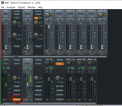
Attached is RME Totalmix screencapture, channel 1 is used as reference (loopback), mic in channel 2.
Attachments
Hi there! I have a fullrange project in hands, its for a vintage (circa 90´s) 6" driver with whizzer. Need to measure its TS parameters to use leonardaudio app for simulation (i may learn another simlation tools also).
I´ve got a umc22 interface and i was thinking to use the soundcard arrangemet that appears here: http://www.artalabs.hr/AppNotes/LIMP_Tutorial_Version_2_4_English.pdf .
The procedure requires one output (UMC22 has headphone and guess line output on the rear) and two inputs (UMC22 has one mic input and one instrument input). I have essentially two doubts:
1) Is there a difference in the measurment depending on output used (headphone or rear guess line level out)?
2) is there a difference in the measurmet depending on wich input (mic or inst) is used for each of the two nodes in the circuit? (one IN goes to interface out and the ref resistor while the other is connected to resistor and speakeer).
Extra: The cables shields and speaker ground should be connected together? Is it important for them to be connected to a real 0v earth voltaje or something like it?
Hope you can help me
All the best
Last edited:
ARTA Help Needed:
(1) When trying to create Directivity Patterns, I keep getting the error that "Error: this .pir file was made with newer version of ARTA!"
- The above statement is incorrect. I'm using ARTA 1.9.3, and the pir files were developed with 1.9.3
(2) In the ARTA Handbook, under Calibration of Microphone - Section 1.5.3, its says:
1. Connect the microphone preamplifier to the soundcard input (left or right).
2. Enter the preamplifier gain.
3. Attach the sound calibrator on the microphone.
4. Press the button 'Estimate mic sensitivity'.
5. If you are satisfied with a measurement, press the button 'Accept'.
- I'm using a Focusrite 2i2 (first gen) as my soundcard and mic pre. My ECM8000 mic is connected to the front mic input using the XLR connector. Do do I just disregard Step 1?
- What does step 2 mean?
- What is a "sound calibrator"? an SPL Meter? If so, I have an analog Radio Shack SPL meter.
ARTA Help Needed:
(1) When trying to create Directivity Patterns, I keep getting the error that "Error: this .pir file was made with newer version of ARTA!"
- The above statement is incorrect. I'm using ARTA 1.9.3, and the pir files were developed with 1.9.3
Please download ARTA software ver. 1.9.3 Update 1. to get correct .pir file reading.
When calibrating microphone:
1) you should set preamplifier gain as is (in Audio device setup). If you change that value you should also change it in Audio device setup.
2) You should attach sound calibrator on microphone. Enter the value of SPL (usually 94dB). Please, just google: "sound calibrator", to get more information how sound calibrator is used.
If you do not have sound calibrator but have an spl meter you can measure SPL in front of some loudspeaker, driven with external sine source (f=1000 Hz). SPL meter have to be used in linear Z or C weighting mode, then enter measured SPL in dialog box and set measured microphone in the same position as SPL mic. Start calibration.
Ivo
more help needed
Ivo,
Updating the to new version reloved the issue. - Thank You
In regards to calibration, I'm hoping you can verify my method.
I only have two hardware items in my measurement setup:
(1) Focusrite 2i2 (first generation)
(2) Dayton Audio - APA150 Integrated Amplifier (Class A/B)
I use the "Semi-Dual" method for making speaker measurements.
I'm performing the following setups to calibrate. Please let me know if you see something wrong:
Step (1) - Click Generate 400Hz Sine Wave
Step (2) - Connect a multimeter to the Left Channel Out (of the Focusrite, not the amp - correct?) and measure voltage. In my setup, with the front knob of the Focusrite turned all the way to the 3 o'clock position, my multimeter reads 0.4 volts.
Step (3) - Click Stop Generator and enter 400 for mV rms and click "Accept"
Step (4) - Loop Left and Right rear outputs to the front of Focusrite
Step (5) - Click "Estimate Peak Input mV" and, once finished click "Accept"
(when performing this Step, I have no idea where to set the input gain on the Focusrite)
Step (6) - Repeat Step 5 for the Right channel and click "Accept"
Step (7) - Unhook the left channel loopback connection and connect the mic (in my case, a Behringer ECM8000 connected via an XLR connection)
Step (8) - Inset mic into a Sound Calibrator - 94db. Leave "Mic Gain" to 1 (because I don't know what else to put). Turn on Sound Calibrator and click "Estimate Mic. Sensitivity"
Step (9) Click "Accept"
Then, when I take a 1-meter distance measurement of a reputable driver, with the multimeter reading 2.83v at the input terminals, my measured SPL magnitude should reasonable approximate (+/- 2 db) manufacturer specs.
However, my reading are too high. The only way I can get it to match is if I turn the Right channel gain up.
What am I doing wrong?
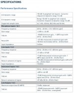
I've added picture of the specs on the Focusrite 2i2 Gen 1
Please download ARTA software ver. 1.9.3 Update 1. to get correct .pir file reading.
Ivo
Ivo,
Updating the to new version reloved the issue. - Thank You
In regards to calibration, I'm hoping you can verify my method.
I only have two hardware items in my measurement setup:
(1) Focusrite 2i2 (first generation)
(2) Dayton Audio - APA150 Integrated Amplifier (Class A/B)
I use the "Semi-Dual" method for making speaker measurements.
I'm performing the following setups to calibrate. Please let me know if you see something wrong:
Step (1) - Click Generate 400Hz Sine Wave
Step (2) - Connect a multimeter to the Left Channel Out (of the Focusrite, not the amp - correct?) and measure voltage. In my setup, with the front knob of the Focusrite turned all the way to the 3 o'clock position, my multimeter reads 0.4 volts.
Step (3) - Click Stop Generator and enter 400 for mV rms and click "Accept"
Step (4) - Loop Left and Right rear outputs to the front of Focusrite
Step (5) - Click "Estimate Peak Input mV" and, once finished click "Accept"
(when performing this Step, I have no idea where to set the input gain on the Focusrite)
Step (6) - Repeat Step 5 for the Right channel and click "Accept"
Step (7) - Unhook the left channel loopback connection and connect the mic (in my case, a Behringer ECM8000 connected via an XLR connection)
Step (8) - Inset mic into a Sound Calibrator - 94db. Leave "Mic Gain" to 1 (because I don't know what else to put). Turn on Sound Calibrator and click "Estimate Mic. Sensitivity"
Step (9) Click "Accept"
Then, when I take a 1-meter distance measurement of a reputable driver, with the multimeter reading 2.83v at the input terminals, my measured SPL magnitude should reasonable approximate (+/- 2 db) manufacturer specs.
However, my reading are too high. The only way I can get it to match is if I turn the Right channel gain up.
What am I doing wrong?
I've added picture of the specs on the Focusrite 2i2 Gen 1
Attachments
Last edited:
On mic. calibration
It is important to note that there are two kind of calibration; voltage sensitivity of i/o channels and microphone sensitivity.
For both types of calibration it is important that they are valid only for one set of volume control position. If you change volume control position calibration have to be repeated. And, this sound like pretty tedious working condition.
Your procedure will give proper calibration for level mode measurements (spectrum, SPL) but not for ratio mode (in dual channel frequency response measurements).
If you are using semi-dual channel configuration, by connecting reference channel to sound-card output (not to power amplifier output) you must enter right channel (ref. ch.) input gain the value that is equal to reciprocal of power amplifier gain (because reference channel gets voltage value that is smaller than power amplifier output).
Ivo
Arta might be over my head to get up and running, but bought a used Steinburg UR22mkII and have been trying to get up to speed in my spare time. I have a very old and very cheap DMM...the calibration directions say to set your multimeter to 2V...I am assuming the output from the sound card should be measured in AC but my DMM only has setting for AC of 200 and 600. Also in the ASIO driver setting window...there is an option for loopback...I'm guessing that needs to be turned off? I know these are very basic questions, but I have not done any electronics measuring in years.
Getting the input/outputs calibrated is kind of a next level already. If you are just starting up it's better to do relative measurements. You will get the resulting graph in dBFS and not in dBSPL, but for most hobby projects that is all you need. Also for crossover design getting the frequency response graph is enough and as long as you keep all in/out levels exact same for woofer/tweeter etc then the relative level difference gets captured and again that is all you need.
Just play the signal from speaker at bit uncomfortably loud level (wear hearing protection) and keep an eye on the level meters for input and adjust mic gain so that the input does not overload even with the loudest speaker unit (usually tweeter).
Keeping it simple like that will get you up and running on important aspects, like frequency response, much faster.
Thank Ergo. I was thinking about just running not calibrated. I also just bought a Clio Pocket, but I think if I can make ARTA work for me it is probably a better long term solution. I don't seem to get much positive feedback from Audiomatica in regards to future additions.