Then no luck, both the Behringer and the Focusrite are sizable boxes. But then again, they have the XLR connectors and phantom power, convenient for measuring with a microphone.
It can be cheap card with line in-out. Most are 24/48. For speakers UCA202 may do the job?
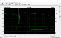
first timer, phase wraps
Hi all,
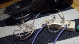
as a friday project I made quickie measurement jig on a plank of wood and tried LIMP for the first time.
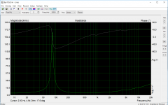
All is ok, except the phase seems to wrap on the impedance peak. Never seen this on other LIMP screenshots. What might cause this, or is this normal?
Also, the impedance peak is mucho less than factory datasheet impedance curve, what might cause this? The driver is FaitalPRO 8pr155
Speaker was on the floor while measuring. Reference resistor is 23.3ohm. Using balanced inputs on my RME babyface using pin2 (probe) and pin3 (ground), grounds attached together (left & right). I calibrated input levels to green, put reference resistor value to measurement setup. I didn't put anything to cable compensation setup, cables from jig to sound card are maybe 30cm long. Speaker cables from amp and to speaker are few meters.
Sorry if this is already shown somewhere, didn't find any hints by googling.
Few attachments to illustrate")
Thanks!
Hi all,
as a friday project I made quickie measurement jig on a plank of wood and tried LIMP for the first time.
All is ok, except the phase seems to wrap on the impedance peak. Never seen this on other LIMP screenshots. What might cause this, or is this normal?
Also, the impedance peak is mucho less than factory datasheet impedance curve, what might cause this? The driver is FaitalPRO 8pr155
Speaker was on the floor while measuring. Reference resistor is 23.3ohm. Using balanced inputs on my RME babyface using pin2 (probe) and pin3 (ground), grounds attached together (left & right). I calibrated input levels to green, put reference resistor value to measurement setup. I didn't put anything to cable compensation setup, cables from jig to sound card are maybe 30cm long. Speaker cables from amp and to speaker are few meters.
Sorry if this is already shown somewhere, didn't find any hints by googling.
Few attachments to illustrate
Thanks!
Attachments
Last edited:
Don't sit the speaker on a table or the floor, this will affect the measurement due to mass loading effects from the surface. Hang it from a wire through one of the screw mounting holes in the frame so that it's hanging in mid air at least half a metre from any other objects. (For example clamp a support wire to a table top or work bench and hang the speaker half way to the floor)
All published driver impedance curves for commercial drivers are taken with the driver suspended in mid air away from large surfaces.
Your phase curve does look odd, I wouldn't expect more than +/- 90 degrees phase shift to occur even with a very high Q resonance.
The impedance measurement is suspect as well, it should not be showing a lower impedance at 5Khz than 10Hz!
Before going any further I would perform some tests with reference resistors.
Replace the speaker with a reference resistor which you have measured accurately with a multi-meter. You should get a perfectly flat line of the correct impedance.
Check this with a few different values of resistor - say 6.8 ohms, 12 ohms and 33 ohms, and also check it with the speaker terminals shorted out to make sure you get 0 ohms.
My guess is that you have a problem with your measurement setup and you will not get a flat line. Probably due to reactive input impedance on the sound card interacting with a voltage divider that is too high in impedance.
Are you sure you haven't made an error in one of your resistive dividers ?
Last edited:
Hi,
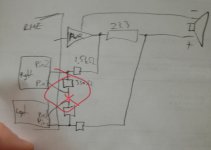
I suppose that your power amplifier has unbalanced output.
In that case you should connect pin 3 of both channel to ground.
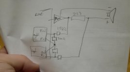
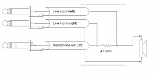
In attachment I send you simple impedance jig that enables impedance measurement without power amplifier. Just use headphone output (RME outputs 3/4) as generator with reference resistor 47 ohms.
Use RME inputs 3 and 4 as unbalanced one.
Best,
Ivo
I suppose that your power amplifier has unbalanced output.
In that case you should connect pin 3 of both channel to ground.
In attachment I send you simple impedance jig that enables impedance measurement without power amplifier. Just use headphone output (RME outputs 3/4) as generator with reference resistor 47 ohms.
Use RME inputs 3 and 4 as unbalanced one.
Best,
Ivo
Attachments
In my previous post I send a simple impedance jig schematic.
The possible question is how to do the calibration procedure of LIMP.
Do:
1) before calibration disconnect loudspeaker.
2) do calibration as described in LIMP manual (use averaging option)
3) after calibration, correct reference resistor with value that is equal to value parallel connection of reference resistor and sound card input resistance.
4) start measurements
This procedure gives good results, you can even correctly measure higher impedance (several kilo ohms).
More detailed explanation I will give in LIMP user manual that will be published next month.
Ivo
Hello Ivo, it would be possible to integrate more than one loudspeaker into the Spatial impulse response group record, I think the measurement would accelerate unless I have a Rotary Table. Loudspeakers could be measured at a precise angle, so I would not have to go with each other separately.
Thank you
Thank you
-I think it depends on what you are using Arta for..
(considering we are on the "multi-way" part of the forum I'll take that to mean Acoustic measurements, and specifically "dual-channel".)
Fig. 1.2:
http://www.artalabs.hr/download/STEPS-user-manual.pdf
This should work at a modest cost:
Studio 26c | Tech Specs | PreSonus
If you want a bit better performance it will cost you double that amount (and require a *Thunderbolt connection):
Clarett 2Pre | Focusrite
You could add the auto-ranger to this for greater capability with electronic measurements:
The L|A Autoranger | Linear Audio NL
*note: they also a USB version, but apparently its latency isn't great (..if that means anything to you).
Last edited:
Question: does Arta (internally with options) handle IEPE piezo-mic.s/actuators/etc. (with Voltage settings)?
Ex. to be used with this:
SpectraPLUS Hardware Recommendations : SpectraPlus.com
Ex. to be used with this:
SpectraPLUS Hardware Recommendations : SpectraPlus.com
Last edited:
Again, depends on what you are using it for, to me the biggest "plug" for SpectraDAC in the acoustic-only measurement would be IF Arta has IEPE settings for certain mic.s and accelerometers:
The SpectraDAC if it Arta has (or will have) IEPE settings within it.
Ex.
https://www.roga-messtechnik.de/roga-instruments_microphones_mp40.pdf
https://www.virtins.com/CA-YD-PDF/IEPE-MIC-14604A.pdf
..and several accelerometers to choose from here:
IEPE Accelerometers, Simulator, Magnetic Mounting Bases, Microphones | Virtins Technology
-and though those mic.s are expensive, they are actually quite inexpensive for what they are where you can easily spend 3 times as much for similar performance from NON-IEPE mic.s.
Last edited:
The bargain purchase for basic acoustic measurements however would be the Studio 25c and one of these:
EMX-7150 Measurement microphone (bulk) - AcousticShop
-slap on a DATS v2 for just plain ease (..as opposed to LIMP + jig) for getting your T/S parameters and Impedance trace really quickly, also good for Rub/Buzz testing.
Dayton Audio DATS V2 Audio Test System 844632094255 | eBay
The total for all 3 should be less than the SpectraDAC alone.
-and of course Ivo's suggested amp for measurements:
the t.amp PM40C – Thomann Nederland
-you could even "throw-in" a cheap accelerometer (plus a plug adapter) to get a better idea of panel resonances:
ATB Shop - Onlineshop
Last edited:
Hello Scott,
I would use the setup to measure tube amplifiers and loudspeakers.
I have the Behringer ECM8000 that I used many years ago with Arta and E-MU 0404
I also have a compensation file for that microphone. I think I could modify that for use in ARTA.
I could use that with the Studio 2C as well I suppose.
Specs are about the same as the E-MU 0404
Maybe if someone had W10 drivers for the EMU0404 I could still use that.
Does the spectraDAC have direct advantages over the Studio 2C?
Exept for the attenuator that is?
Johan
I thought about adding something like this.
Buy speaker measurement kit and get free shipping on AliExpress.com
Only attenuation would still be a problem I think
It has a potmeter on the input though.
Buy speaker measurement kit and get free shipping on AliExpress.com
Only attenuation would still be a problem I think
It has a potmeter on the input though.
Last edited:
...Maybe if someone had W10 drivers for the EMU0404 I could still use that...
If that older driver is a exe-file then try rightclick and set combability to that older version before you execute install, that works perfect in W10 for my old M-Audio AP192 card.
Hello,
I have been using a USB UMIK and REW for single channel measurements to use with Vituix CAD for speaker design and my phase measurements are not accurate enough.
I would like to use ARTA for dual channel measurements.
My current output setup is a Soundblaster Audigy 5/Rx sound card with optical out to a Topping D50 DAC to an Adcom preamp to Adcom power amp for sound out. Recording would still be with the USB UMIK.
How can I make this a dual channel setup for better phase recording with ARTA?
Thank you,
David.
Does the spectraDAC have direct advantages over the Studio 2C?
Exept for the attenuator that is?
Johan
This is something to ask here:
https://www.diyaudio.com/forums/equipment-and-tools/
I thought about adding something like this.
Buy speaker measurement kit and get free shipping on AliExpress.com
This is basically that "jig" I mentioned + a poorly "fed" op-amp. It might be very serviceable, but again: I prefer the DATS (and more substantive amp) already mentioned.
..Recording would still be with the USB UMIK.
That mic has a "DAC" built-in, (I believe) as a result: no dual-channel capability.