Please both, not instead please.please allow display of relative harmonic level in dBr instead of %
I don't like dBr (at all), but I know other people do

Good morning.
I would respectfully ask for the ability to leave the legend up on a graph for printing and review. I find that when comparing overlays, I have to repeatedly refer back to the legend to remember what each is representing. Thank you very much.
I would respectfully ask for the ability to leave the legend up on a graph for printing and review. I find that when comparing overlays, I have to repeatedly refer back to the legend to remember what each is representing. Thank you very much.
Dear community,
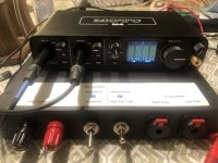
I have bought the MOTU M4 as it comes highly praised on several forums.
When I make the initial tests of the sound card using loop cables, I simply don’t understand a thing.
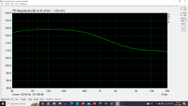
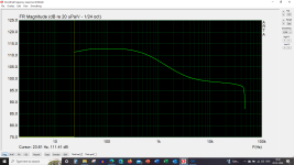
Much to my surprise I find a THD+N level of 0.23 % for a -3 dBFS,, and if I investigate the sound cards frequency response, I also end up with something, that simply cannot be right.
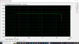
Attached you can see the frequency graph in loopback mode. It is taken as a simple IR and converted to FR.
Setup on the M4 is loop cables out of Monitor 1-2 on backside of the M4 and into Input 1 and 2 on the front. Monitor buttons are not activated and Input Monitor Mix potmeter is turned all counterclockwise to "Input". ARTA box is not in the loop.
Any ideas on the correct setup for the M4 to work as intended?
I have bought the MOTU M4 as it comes highly praised on several forums.
When I make the initial tests of the sound card using loop cables, I simply don’t understand a thing.
Much to my surprise I find a THD+N level of 0.23 % for a -3 dBFS,, and if I investigate the sound cards frequency response, I also end up with something, that simply cannot be right.
Attached you can see the frequency graph in loopback mode. It is taken as a simple IR and converted to FR.
Setup on the M4 is loop cables out of Monitor 1-2 on backside of the M4 and into Input 1 and 2 on the front. Monitor buttons are not activated and Input Monitor Mix potmeter is turned all counterclockwise to "Input". ARTA box is not in the loop.
Any ideas on the correct setup for the M4 to work as intended?
Attachments
Member
Joined 2003
Member
Joined 2003
Ok, so loopback measurement is as simple as it gets, so your result is quite confusing. Perhaps a bit more detail is required.
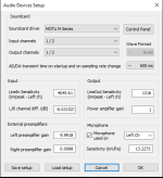
Loopback cable is TRS type cable, from monitor out 1 to input 1 (left)? ARTA should be set to use ASIO driver in the preference, like this:

For measurement, you can use impulse response type of measurement, or realtime measurement "FR1". Disable frequency response compensation and measure.
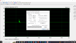
Impulse response measurement window for sine sweep:

For impulse response, no gate applied, response should look similar to this:

Loopback cable is TRS type cable, from monitor out 1 to input 1 (left)? ARTA should be set to use ASIO driver in the preference, like this:
For measurement, you can use impulse response type of measurement, or realtime measurement "FR1". Disable frequency response compensation and measure.
Impulse response measurement window for sine sweep:
For impulse response, no gate applied, response should look similar to this:
Thanks for taking the time to help figuring this out @DcibeL
I confirm that ASIO drivers are set to 1-2 output and 1-2 as input.
Frequency response compensation of microphone is disabled.
Input Monitor Mix is set to full Playback.
The result is the same as before.
I confirm that ASIO drivers are set to 1-2 output and 1-2 as input.
Frequency response compensation of microphone is disabled.
Input Monitor Mix is set to full Playback.
The result is the same as before.
Attachments
Member
Joined 2003
Same result on both left and right front input ? My next comment would be to check your cabling, however I assume you've used the same cabling for input 3/4 test above.
Unrelated to your problem, but sweep FFT length is short, as is window FFT length. Increasing will provide higher resolution of frequency response, especially at low freq.
Unrelated to your problem, but sweep FFT length is short, as is window FFT length. Increasing will provide higher resolution of frequency response, especially at low freq.
Member
Joined 2003
Get your RMA form ready...
FWIW If I set up my M4 the same way you have, input is clipping at -3dB output. It's hard to see your actual input dBFS since you are showing as SPL scale. In any case, just as above, unrelated to your FR problem, in fact clipped input should only be flatter
FWIW If I set up my M4 the same way you have, input is clipping at -3dB output. It's hard to see your actual input dBFS since you are showing as SPL scale. In any case, just as above, unrelated to your FR problem, in fact clipped input should only be flatter
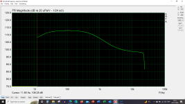
If I use outputs 3 an 4 and inputs 3 and 4 I will get a flat frequency curve as shown earlier in post #1,409
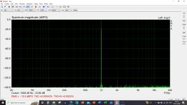
Even though I cannot make any adjustments to the levels, if I test the M4 with these outputs and inputs then I get a nice low THD+N.
Signal when estimating is some -10 dB lower than required, so not really representative.
Even though I cannot make any adjustments to the levels, if I test the M4 with these outputs and inputs then I get a nice low THD+N.
Signal when estimating is some -10 dB lower than required, so not really representative.
Attachments
One question out of curiosity (and trying to understand):
When I use outputs 1 and 2 and turn the large monitor knob to the left of the display, shouldn´t the meters react?
Mine stays as if there is full output on 1 and 2. I can toggle the Monitor knob without any effect.
If I measure output voltage it is reacting to the adjustments, but meters are not..
When I use outputs 1 and 2 and turn the large monitor knob to the left of the display, shouldn´t the meters react?
Mine stays as if there is full output on 1 and 2. I can toggle the Monitor knob without any effect.
If I measure output voltage it is reacting to the adjustments, but meters are not..
Member
Joined 2003