Hi,
I have recently acquired a pair of Parmeko LSU/10 Broadcast monitors used in the BBC studios in the 1950's and 1960's.
I am looking for any information about them.
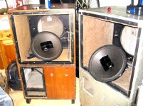
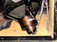
They contain a LS-1 15" co-axial driver with an (added by the BBC) Lorenz LPH 65 super tweeter. The co-axial tweeter has a six segment cellular horn. The Lorenz tweeter has a clear poly cone.
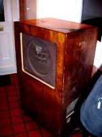
There is a space in the cabinets for a tube amplifier.
Any and all help/information would be very much appreciated.
I have recently acquired a pair of Parmeko LSU/10 Broadcast monitors used in the BBC studios in the 1950's and 1960's.
I am looking for any information about them.
They contain a LS-1 15" co-axial driver with an (added by the BBC) Lorenz LPH 65 super tweeter. The co-axial tweeter has a six segment cellular horn. The Lorenz tweeter has a clear poly cone.
There is a space in the cabinets for a tube amplifier.
Any and all help/information would be very much appreciated.
Attachments
My word! How on earth did a pair of those wardrobes make their way across the Atlantic?
The amplifier was an LSM/8 which was a slightly modified Leak TL12 using triode-strapped KT66 to produce about 15W. I've never seen an LSU/10 with those tweeters - the one we had (when I was at BBC Broadcasting House) had a pair of Celestion HF1300 mounted in front of the 15" driver.
The amplifier was an LSM/8 which was a slightly modified Leak TL12 using triode-strapped KT66 to produce about 15W. I've never seen an LSU/10 with those tweeters - the one we had (when I was at BBC Broadcasting House) had a pair of Celestion HF1300 mounted in front of the 15" driver.
EC8010
They made thier way across the pond with the help of a whole lot of money and Virgin Atlantic airways.")
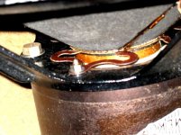
In this photo you can see the tweeter clearly.
According to Edward Pawley's book All the LSU/10's were augmented with the Lorenz tweeters when the 405 line television standard was introduced.
Thanks
Tom
They made thier way across the pond with the help of a whole lot of money and Virgin Atlantic airways.
In this photo you can see the tweeter clearly.
According to Edward Pawley's book All the LSU/10's were augmented with the Lorenz tweeters when the 405 line television standard was introduced.
Thanks
Tom
Attachments
They flew?! Ours definitely had Celestion HF1300 - perhaps a later modification. (By the way, 405 line television predated the LSU10 - the Marconi/EMI 405 line and the Baird system were in use in parallel before WWII.)
Here's something that may be of interest.
Instruction S.8
Cabinet LB/8 (Fig. 1.3)
The cabinet is constructed in the form of a vented enclosure which gives a smoother and wider-range bass response than the box baffles used hitherto. The rear of the cabinet is completely boxed in and an opening or vent in the form of a rectangular hole is provided in the base. This vent opens into a cavity between the base and the floor and is bounded by the plinth which supports the cabinet. The plinth is arranged as three sides of a square and directs sound waves transmitted through the vent outwards from the front of the cabinet. The vent and associated cavity have the nature of an acoustic inductance whilst the air enclosed inside the cabinet behaves as a capacitance and the dimensions are chosen to give resonance at the lowest frequency it is desired to reproduce. Low-frequency sound waves generated at the rear of the loudspeaker diaphragm are transmitted through the vent and, over a limited frequency range, are in phase with the radiation from the front of the loudspeaker. The design is such that the useful range of the loudspeaker is extended downwards by about half an octave.
To prevent high-frequency sound waves being transmitted through the vent the upper half of the cabinet is lined with about 1¼ inch thick slag wool. This is obtained in pre-formed slabs which are stuck to the sides of the cabinet and are then covered with a layer of carpet loom felt. Such treatment is effective in suppressing high-frequency sound waves but does not sufficiently eliminate low-frequency vertical air-column resonance which occurs at about 120 c/s. This is suppressed by three ¼ inch layers of carpet loom felt stretched horizontally across the centre of the cabinet where the standing waves have maximum particle velocity. Very little high-frequency radiation reaches the lower half of the cabinet and the only acoustic treatment necessary is provided by a single layer of carpet loom felt. If a thin layer of absorbing material were attached directly to the walls the absorption would be low because particle velocity is a minimum close to a reflecting surface. For this reason the felt in the lower half of the cabinet is attached to battens to space it about 1 ¼ inch from the walls.
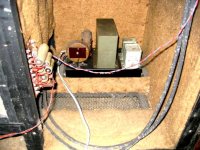
The loudspeaker amplifier LSM/8 is situated on a shelf within a small compartment in the lower half of the loudspeaker cabinet and at the right-hand side (viewed from the front) and the gain control is accessible through a hole in the lower right-hand panel. This panel and the rear panel adjacent to the amplifier have windows of expanded metal to provide ventilation and a baffle is fitted to the amplifier chassis to direct hot air out of the amplifier compartment. Before the amplifier can be removed the side and rear panels of the amplifier compartment must be detached. These are each held in place by a number of screws and the amplifier itself is secured to the shelf by four bolts. There is, of course, no need for acoustic treatment of the interior of the amplifier compartment but the outside is lagged with three layers of carpet felt.
Here's something that may be of interest.
Instruction S.8
Cabinet LB/8 (Fig. 1.3)
The cabinet is constructed in the form of a vented enclosure which gives a smoother and wider-range bass response than the box baffles used hitherto. The rear of the cabinet is completely boxed in and an opening or vent in the form of a rectangular hole is provided in the base. This vent opens into a cavity between the base and the floor and is bounded by the plinth which supports the cabinet. The plinth is arranged as three sides of a square and directs sound waves transmitted through the vent outwards from the front of the cabinet. The vent and associated cavity have the nature of an acoustic inductance whilst the air enclosed inside the cabinet behaves as a capacitance and the dimensions are chosen to give resonance at the lowest frequency it is desired to reproduce. Low-frequency sound waves generated at the rear of the loudspeaker diaphragm are transmitted through the vent and, over a limited frequency range, are in phase with the radiation from the front of the loudspeaker. The design is such that the useful range of the loudspeaker is extended downwards by about half an octave.
To prevent high-frequency sound waves being transmitted through the vent the upper half of the cabinet is lined with about 1¼ inch thick slag wool. This is obtained in pre-formed slabs which are stuck to the sides of the cabinet and are then covered with a layer of carpet loom felt. Such treatment is effective in suppressing high-frequency sound waves but does not sufficiently eliminate low-frequency vertical air-column resonance which occurs at about 120 c/s. This is suppressed by three ¼ inch layers of carpet loom felt stretched horizontally across the centre of the cabinet where the standing waves have maximum particle velocity. Very little high-frequency radiation reaches the lower half of the cabinet and the only acoustic treatment necessary is provided by a single layer of carpet loom felt. If a thin layer of absorbing material were attached directly to the walls the absorption would be low because particle velocity is a minimum close to a reflecting surface. For this reason the felt in the lower half of the cabinet is attached to battens to space it about 1 ¼ inch from the walls.
The loudspeaker amplifier LSM/8 is situated on a shelf within a small compartment in the lower half of the loudspeaker cabinet and at the right-hand side (viewed from the front) and the gain control is accessible through a hole in the lower right-hand panel. This panel and the rear panel adjacent to the amplifier have windows of expanded metal to provide ventilation and a baffle is fitted to the amplifier chassis to direct hot air out of the amplifier compartment. Before the amplifier can be removed the side and rear panels of the amplifier compartment must be detached. These are each held in place by a number of screws and the amplifier itself is secured to the shelf by four bolts. There is, of course, no need for acoustic treatment of the interior of the amplifier compartment but the outside is lagged with three layers of carpet felt.
Attachments
http://www.german-vintage-loudspeak...menu_page/page_main.php?nojs=1&hp2_nav_id=109
````````````````````````````````````````````````
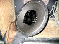
could you post a pic of the backs of the drivers?
```````````````````````````````````````````````
http://www.oldsms.co.uk/gear/typeb.php
````````````````````````````````````````````````
could you post a pic of the backs of the drivers?
```````````````````````````````````````````````
http://www.oldsms.co.uk/gear/typeb.php
tom1356 said:I forgot to mention these are the speakers used at Abbey Road studios to record The Beatles.
That seems rather unlikely since the LSU/10 was an in-house BBC design. Besides, I think the Beatles are wildly over-rated.
Here's some more information that you might find helpful. Note that the crossover unit is not the one in the LSU/10, but BBC crossovers followed an evolution of design, so it might be similar. And before you ask, I don't have Fig. 2 (LSM/8 circuit diagram)
Instruction S.8
Section 1
Filter Unit F/28 (Fig. 1.2)
The high-frequency unit of the loudspeaker LS/1 must not receive low-frequency inputs because the large amplitudes which can be developed at these frequencies might cause damage. It is also undesirable for the cone unit to radiate high frequencies because these would cause interference with the output from the h.f. unit. A filter unit, F/28, is therefore included between amplifier and loudspeaker to ensure that only high-frequency signals are fed to the h.f. unit and only low frequencies, to the l.f. unit. The frequency at which the cross-over occurs is determined by the design of the loudspeaker and is 1,200 c/s for the LS/1.
The filter is basically a simple series type the main components being L1C1 and L2C2. L1 and C2 are connected across the input terminals and resonate at 1,200 c/s. At this frequency equal voltages are developed across L1 and C2 but as frequency is reduced the reactance of C2 increases, causing a greater voltage to be fed to the l.f. unit of the loudspeaker, and the reactance of L1 falls, causing a smaller voltage to be delivered to the h.f. unit. The performance of the filter is improved by the inclusion of L2 which, in conjunction with the l.f. speech-coil impedance, forms a potential divider which further reduces the signal fed to the l.f. unit at frequencies above 1,200 c/s and by the inclusion of C1 which similarly attenuates the signal fed to the h.f. unit at frequencies below 1,200 c/s.
The h.f. unit is more efficient than the l.f. unit and, with a filter consisting simply of L1C1 and L2C2, the output from the loudspeaker shows a sharp increase or " step." as frequency is increased through 1,200 c/s. To eliminate this, the components R2 and R4 are introduced ; these reduce the output from the h.f. unit to approximately the same value as that from the l.f. unit at frequencies near the cross-over value. The attenuation so introduced is too great at high frequencies and a fixed capacitor C4 is shunted across R2 to reduce the loss at these frequencies.
To eliminate a peak in the loudspeaker output at about 12,000 c/s a parallel-tuned circuit L3C3 is inserted in series with the h.f. unit and the Q of the circuit is reduced to the desired value by the fixed resistor R3.
The input impedance of the filter unit with the loudspeaker in circuit has a minimum value of approximately 4 ohms and the secondary windings of the LSM/8 output transformer are connected to match this load. When the LS/1 is used in conjunction with an MPA/l amplifier the two secondary windings on the output transformer should be connected in parallel as for a 4-ohm load.
The output impedance of the LSM/8 is less than that of the MPA/1 and when an LSM/8 is used with the filter unit and loudspeaker a 1-ohm resistor Rl is inserted in one leg df the filter input circuit. This resistor is short-circuited when an MPA/1 is used to ensure that the filter unit is always effectively fed from the same source impedance.
Loudspeaker Amplifier LSM/10
Certain LSU/10 units are now fitted with a commercial amplifier type LSM/10 in place of the LSM/8. The circuit of the LSM/10 is basically similar to that of the LSM/8 and is given in Fig. 2 (Serial Nos. 101-470) and Fig. 2A (Serial Nos. 471 onwards).
Attachments
EC8010
You have quickly become my hero.
I agree the Beatles are over-rated. I thought the reference might jog some memories.
The information comes from Alan Shaw at Harbeth and was independently confirmed by an ex white coat at Abbey Road.
Strong BBC/ EMI ties may have been responsible.
As far as the 405 line TV signal. Of course you are right. I went back and re-read Pawley. He says that the LS-1 has a dip at 10125Hz which made it hard to hear a whistle generated by the 405 line TV signal.
When this was discovered all the LSU/10's that needed to be were converted to three ways with the Lorenz tweeters. Crossover point was 7000Hz.
Thank you so much for your time and effort. The information you have supplied is amazing. I really appreciate it!
Cheers
Tom
Do I have to wear spangly tights?
If Alan Shaw says it's correct then I believe it. As you say, there were close ties between the BBC and EMI during 405 line "high definition" (oh yes, that's what it was called) development. Evidently, the ties went further than video.
I've been looking for the Harwood IEE paper I had that I'm sure made some passing reference to the LSU/10, but it seems to have disappeared. If I don't find it, you now have all the LSU/10 information that I have. I'm glad you find it useful.
tom1356 said:I forgot to mention these are the speakers used at Abbey Road studios to record The Beatles.
Pretty cool huh?
Do you mean that this is the kind of speaker was used at Abbey Road, or this actual pair?
According to this page the Tannoy 15" MG was used for mixing. Though Troels didn't seem to think the Beatles sounded that hot being played through them. There's the adage that the mixing engineer doesn't care for speakers that are necessarily accurate but only predictable. Be interesting to know if the recording monitors are different.
many thanks for the pictures.
the "old studio managers" site says these were
made by tannoy, was wondering, as they do not
appear as other tannoys i've seen (pictures of).
`````````````````````````````````````````````
off topic-
http://www.railpictures.net/viewphoto.php?id=135674
the "old studio managers" site says these were
made by tannoy, was wondering, as they do not
appear as other tannoys i've seen (pictures of).
`````````````````````````````````````````````
off topic-
http://www.railpictures.net/viewphoto.php?id=135674
Re: Do I have to wear spangly tights?
EC8010
The tights are an option but if you do decide to don them please send along pictures.
Alan has a white paper that D.E.L. Shorter (the designer) wrote for the AES about the LSU/10, and he also has the original patent. He is a big fan of these speakers and has promised to get me those documents when he can.
He has offered to buy these but they are not for sale at this time.
Thanks again.
Tom
EC8010 said:If Alan Shaw says it's correct then I believe it. As you say, there were close ties between the BBC and EMI during 405 line "high definition" (oh yes, that's what it was called) development. Evidently, the ties went further than video.
I've been looking for the Harwood IEE paper I had that I'm sure made some passing reference to the LSU/10, but it seems to have disappeared. If I don't find it, you now have all the LSU/10 information that I have. I'm glad you find it useful.
EC8010
The tights are an option but if you do decide to don them please send along pictures.
Alan has a white paper that D.E.L. Shorter (the designer) wrote for the AES about the LSU/10, and he also has the original patent. He is a big fan of these speakers and has promised to get me those documents when he can.
He has offered to buy these but they are not for sale at this time.
Thanks again.
Tom
jdybnis said:
Do you mean that this is the kind of speaker was used at Abbey Road, or this actual pair?
According to this page the Tannoy 15" MG was used for mixing. Though Troels didn't seem to think the Beatles sounded that hot being played through them. There's the adage that the mixing engineer doesn't care for speakers that are necessarily accurate but only predictable. Be interesting to know if the recording monitors are different.
jdybnis
This type of speaker was used in the control room to monitor the recording. These are not those speakers. This pair was acquired in the early 1980's from a BBC Studio Manager.
I'm sure Abbey Road must have used Tannoys in certain locations. You also have to keep in mind the word Tannoy is almost a generic term for speaker to some people in the UK.
Thanks
Tom
tomtt said:many thanks for the pictures.
the "old studio managers" site says these were
made by tannoy, was wondering, as they do not
appear as other tannoys i've seen (pictures of).
`````````````````````````````````````````````
off topic-
http://www.railpictures.net/viewphoto.php?id=135674
tomtt
They were made by Parmeko. I have talked to an engineer at Parmeko in the 1950's-1960's. His job was to test the High Frequency drivers.
He told me about their testing procedure and how they had a special cabinet made for quick changes.
He aslo told me about how in 1958 at one of the Hotel Russell Hi-Fi Fairs they were introducing their "Altobass 2000" drivers which were a 12" derivative of the LS-1.
He said Guy R. Fountain (Mr. Tannoy) stopped by thier booth. He listened for a while then he nodded to Parmeko's dishevelled Sales Manager and said "not bad - not bad at all".
Thanks
tom
- Status
- This old topic is closed. If you want to reopen this topic, contact a moderator using the "Report Post" button.
- Home
- Loudspeakers
- Multi-Way
- 1950's Parmeko Co-axial 15" BBC speakers