I have just got a pair of speakers with dynaudio 17w75xl and d28/2. The construction of the crossover includes a 1.2mh and 2.2u for the woofer, a 0.68mh and 3.9u for the tweeter. Because the crossover is not designed by a professional, but a amateur. I want to know this crossover is suit for this speaker or not. What is the crossover frequency of it? Should I add a L-pad to damp the tweeter driver?
Thanks for the reply in advance.
Thanks for the reply in advance.
It is generally understood that Dynaudio recommended 6.8R and 20uF as the zobel for impedance correction:
This thread may help:
Dynaudio 17W75-XL and D28/2 Crossover and bass reflex help
This thread may help:
Dynaudio 17W75-XL and D28/2 Crossover and bass reflex help
hello to all and thank you for your answers.
I have understood the principle of using the manufacturer's recommendations, but there are things that I do not understand about the proposed diagrams.
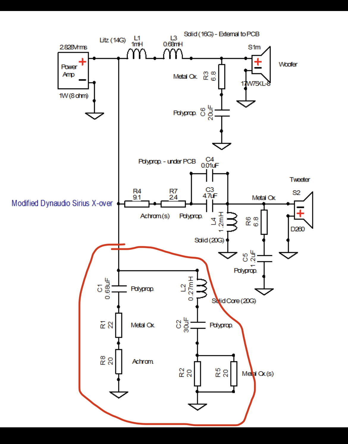
I used as an example the diagram found in the post sited previously, I do not understand the part at the bottom that I have circled in red.
can you explain the usefulness to me please?
I would also like to understand why to put 2 coils (L1 + L3) in serie serie for the 17w75 instead of only one of added value…
Thx
")
https://www.diyaudio.com/forums/attachment.php?attachmentid=990000&stc=1&d=1634117916
I have understood the principle of using the manufacturer's recommendations, but there are things that I do not understand about the proposed diagrams.
I used as an example the diagram found in the post sited previously, I do not understand the part at the bottom that I have circled in red.
can you explain the usefulness to me please?
I would also like to understand why to put 2 coils (L1 + L3) in serie serie for the 17w75 instead of only one of added value…
Thx
https://www.diyaudio.com/forums/attachment.php?attachmentid=990000&stc=1&d=1634117916
Attachments
I do not understand the part at the bottom that I have circled in red.
seems to be a impedance linearization network.
I would also like to understand why to put 2 coils (L1 + L3) in serie serie for the 17w75 instead of only one of added value…
probably just because someone had these values available.
also consider that the resistance of the inductors has some influence to the crossover and the loudspeaker TSP (this may be another reason why to use two inductors).
Thank you for your fast answer
what I don’t understand (sorry I'm a beginner) is that the RC correction (Zobel network) is already used to compensate for the rise in impedance due to the inductance of the coil.
We have R3 of 6.8ohm + C6 of 20uf for the 17w75 and R6 of 6.8ohm + C5 of 1.2uf for the D260
what I don’t understand (sorry I'm a beginner) is that the RC correction (Zobel network) is already used to compensate for the rise in impedance due to the inductance of the coil.
We have R3 of 6.8ohm + C6 of 20uf for the 17w75 and R6 of 6.8ohm + C5 of 1.2uf for the D260
what I don’t understand (sorry I'm a beginner) is that the RC correction (Zobel network) is already used to compensate for the rise in impedance due to the inductance of the coil.
you could either ask the author of the scheme or make a simulation to understand the network ...
I would try the circuit suggested by Lojzek in the thread I quoted:
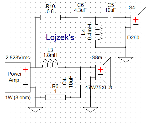
Dynaudio 17W75-XL and D28/2 Crossover and bass reflex help
He's usually a safe pair of hands!
Impedance correction could take us into some deep water. It often gets into trouble because it doesn't allow for bafflestep (bass boost at low frequency to correct the box).
I don't want to go into it.
Flat Impedance and Flat Power response design.
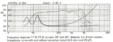
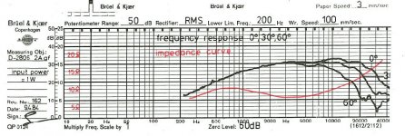
Hi, unless you have some frequency response and impedance measurements/curves for the drivers in this cabinet (or those of the raw drivers), there is not much to be gained from any of these schematics as it is not possible to say what response is being produced; why certain correction circuits are used, what level of attenuation is needed, etc. Or I suppose you could do your best by ear.
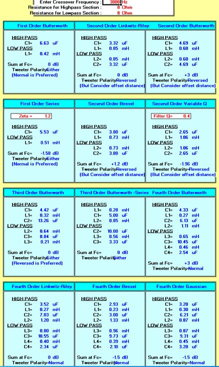
Edit: found a spec sheet for the woofer https://site.diy-loudspeakers.com/i...peakers/dynaudio/WOOFERS/DYNAUDIO_17W75XL.pdf and the tweeter https://site.diy-loudspeakers.com/i...speakers/dynaudio/TWEETERS/DYNAUDIO_D28AF.pdf
One could plug these into software and start from there.
Edit: found a spec sheet for the woofer https://site.diy-loudspeakers.com/i...peakers/dynaudio/WOOFERS/DYNAUDIO_17W75XL.pdf and the tweeter https://site.diy-loudspeakers.com/i...speakers/dynaudio/TWEETERS/DYNAUDIO_D28AF.pdf
One could plug these into software and start from there.
Last edited:
There is impedance compensation both before and after the crossover, serving different purposes. It is safest to not use the components in red.is that the RC correction (Zobel network) is already used to compensate for the rise in impedance due to the inductance of the coil.
motokok, most folks here don't know Ohm's Law from a hole in the ground! I don't mean that unkindly. We are largely a get-you-up-and-running clinic, without too much technical stuff.
To get a simulator running with microphones and all that is just not going to happen for the average person. Never mind all the intricasies of different order filters...
Trust me, a well-behaved 6" bass and tweeter like the Dynaudio stuff is something people like Lojzek can do with his eyes shut. I and AllenB know a bit about it too. Try Lojzek's circuit. It is perfect for preludes' application and exact drivers. What it isn't is first order electrical slopes. But I have never seen Lojzek put a foot wrong.
Well, I did my best to trace the spec sheets; better than nothing. The woofer spec sheet confirms the RC circuit values they recommend. These curves look suspiciously linear!
Attachments
Hello and sincerely thank you all for your contributions. It is true that I like to understand a pattern well before applying it and often I leave with more questions than answers when I try techniques in my corner.
I will therefore base my theoretical diagram on your experiences and advice for these drivers.
I will then try to flesh it out using simulation and ear blindtesting using impedence compensation (part circled in red).
I hope I haven't polluted Ray's post too much
I will therefore base my theoretical diagram on your experiences and advice for these drivers.
I will then try to flesh it out using simulation and ear blindtesting using impedence compensation (part circled in red).
I hope I haven't polluted Ray's post too much
I have just got a pair of speakers with dynaudio 17w75xl and d28/2. The construction of the crossover includes a 1.2mh and 2.2u for the woofer, a 0.68mh and 3.9u for the tweeter. Because the crossover is not designed by a professional, but a amateur. I want to know this crossover is suit for this speaker or not. What is the crossover frequency of it? Should I add a L-pad to damp the tweeter driver?
Thanks for the reply in advance.
Don't worry about ray! He never got an answer anyway. Probably married now, speakers collecting dust in the garage because they have low WAF, and putting up kitchen shelves for SHE WHO MUST BE OBEYED...
As it goes, IMO, he probably could have used an L-Pad to bring down the tweeter. But nobody uses L-Pads any more. Crackly things. Just an attenuating resistor.
Seen one speaker, you seen them, all is my approach:
Visaton-Monacor 2 way sealed simple loudspeaker build plans
86dB, 5.1R DCR 8 ohm 6" bass and 90dB 5.3R DCR 8 ohm 1" tweeter? 15-20L box. Port about 2"x4". Bit of stuffing.
Looks tidy enough response. 5.1R/20 Ohms impedance at 10kHz on bass, so Zobel is 6.8/20uF by my reckoning. You could apply a notch around 5kHz on the bass, but that is component heavy. Attenuation on tweeter will be about 6.8R for 6dB.
How hard can it be? But I would use Lojzek's idea. I am sure he simulated the speaker. He knows Dynaudio stuff. All this 6dB slope stuff is just audio hoey. Doesn't work like that anyway.
Good luck with this. Good drivers. Suitable for a medium room.
Attachments
- Home
- Loudspeakers
- Multi-Way
- crossover frequency