Sorry if this is the wrong section...
I know this is easy for most of you, but I'm a beginner. I'm trying to find some kind of schematic for a 4-way speaker selector switch so that I can incorporate it into an automation project using a computer. I cannot find anything even after an extensive internet search and a search of this forum.
Can anyone help, or point me in the right direction? Thanks in advance!
I don't have a schematic for you, but what you want to do does not sound too hard. I don't know about connecting it to the computer though.
One way to do it would be to use relays to select the speakers. If you want to 4-way selector that would mean switching 8 speakers two at a time, right? So you could use 8 double pole latching relays and use the PC to select which ones to latch and release. To select pair 1 the PC would send a signal (5 or 12 volts) to latch the two relays for pair 1 and at the same time send a signal to release or unlatch the relays for pairs 2, 3, and 4. Just need to make sure the relays can handle the current going through them from the amplifier.
This does not take into account speaker impedences, so only one pair can be driven without increasing the load to the amplifier.
Thanks for the reply. That is exactly what I had in mind for the control section.
The problem is I want to be able to use from 1 to all 4 of the speakers at any one time. The switch I am currently using (just a standard radio shack variety) will allow me to do that. My (cheap) amplifier doesn't seem to mind, so I assume (perhaps incorrectly) that it is doing the impedance matching already. That is the part of the circuit I'm not sure how to build and cannot find anywhere.
The problem is I want to be able to use from 1 to all 4 of the speakers at any one time. The switch I am currently using (just a standard radio shack variety) will allow me to do that. My (cheap) amplifier doesn't seem to mind, so I assume (perhaps incorrectly) that it is doing the impedance matching already. That is the part of the circuit I'm not sure how to build and cannot find anywhere.
What is the part number of the switch from Radio Shack (assuming that it is currently being sold)? If this selector switch allows you to operate 4 pairs of speakers simultaneously, my guess would be that either the selector is inserting resistance in series with the speakers (not likely) or making a parallel connection of two series-connected speakers in each channel.
Are the speakers that you are using raw drivers or speaker systems including passive crossover networks?
Are the speakers that you are using raw drivers or speaker systems including passive crossover networks?
Digging up a relevant thread for this current project (info down the post)...
The Radio Shack type box that the OP is using ADDS RESISTANCE to each of the additional switched on speaker pairs to keep the impedance minimum in check for most amplifiers. This affects more than sensitivity. It affects bass alignment, etc.
Some of these switches use inductive impedance matching autoformers that affect more than just impedance. I think the Rat-Shack box is just that of resistive loading.
To keep speaker performance in optimal condition, and to keep the amplifier happy; I recommend a pro-amplifier or high-current home-amp that is stable to 2 ohms or lower, or the OP will not be able to have 4 pairs in parallel as he is possibly intending.
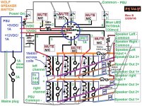
In that mindset, the preliminary project as I'm presenting herein has the possibility to work as the OP intends, if the 2PDT switch is replaced by 4 individual SPST relay-activation switches, and adds 2 identical relays. BUT- the LED indicator circuit will need a rework; Subbing in some 12V LED assemblies per switch will sub in, and the 5V PSU section will not be needed. Again- this is doable IF the amp is 2 ohm stable for 4x 8 ohm speaker pairs, and 1 ohm stable for 4x 4 ohm speaker pairs. Otherwise, I would not recommend this course of action.
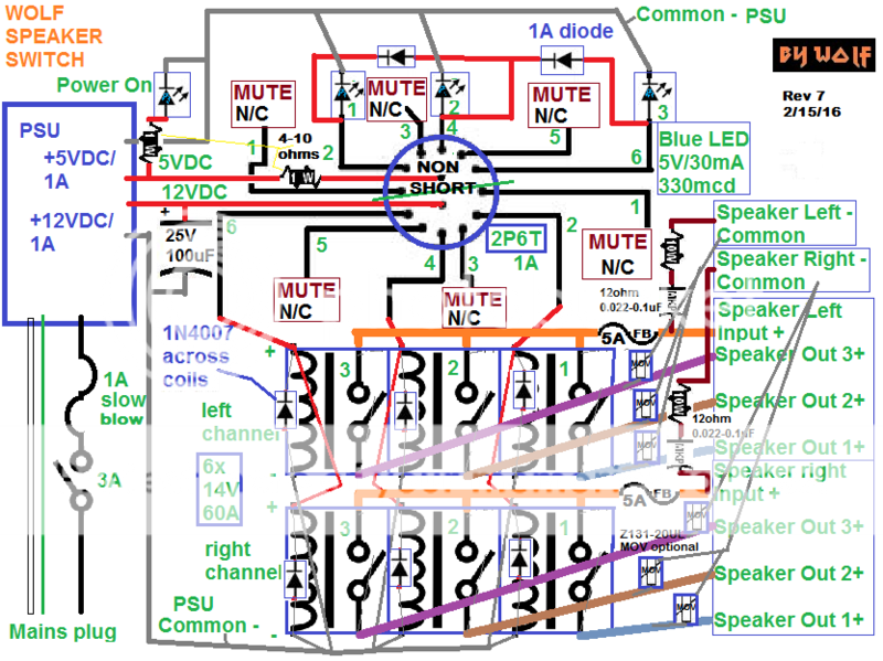
Here is where I'm at thus far:
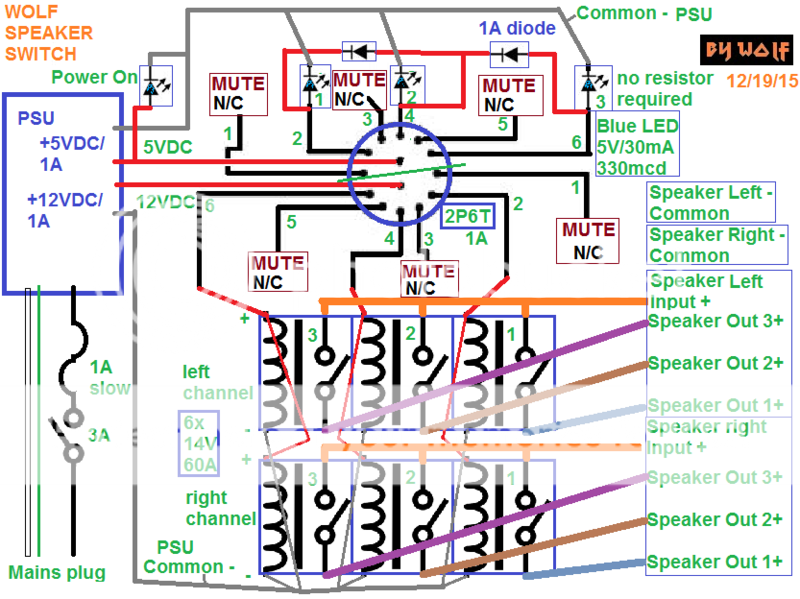
LEDs should count 1-2-3 when switching pairs. Muting in between to hot-swap pairs without killing/shutting-off the amp. This is for one pair in operation per selection.
I think it looks solid,
Wolf
The Radio Shack type box that the OP is using ADDS RESISTANCE to each of the additional switched on speaker pairs to keep the impedance minimum in check for most amplifiers. This affects more than sensitivity. It affects bass alignment, etc.
Some of these switches use inductive impedance matching autoformers that affect more than just impedance. I think the Rat-Shack box is just that of resistive loading.
To keep speaker performance in optimal condition, and to keep the amplifier happy; I recommend a pro-amplifier or high-current home-amp that is stable to 2 ohms or lower, or the OP will not be able to have 4 pairs in parallel as he is possibly intending.
In that mindset, the preliminary project as I'm presenting herein has the possibility to work as the OP intends, if the 2PDT switch is replaced by 4 individual SPST relay-activation switches, and adds 2 identical relays. BUT- the LED indicator circuit will need a rework; Subbing in some 12V LED assemblies per switch will sub in, and the 5V PSU section will not be needed. Again- this is doable IF the amp is 2 ohm stable for 4x 8 ohm speaker pairs, and 1 ohm stable for 4x 4 ohm speaker pairs. Otherwise, I would not recommend this course of action.
Here is where I'm at thus far:

LEDs should count 1-2-3 when switching pairs. Muting in between to hot-swap pairs without killing/shutting-off the amp. This is for one pair in operation per selection.
I think it looks solid,
Wolf
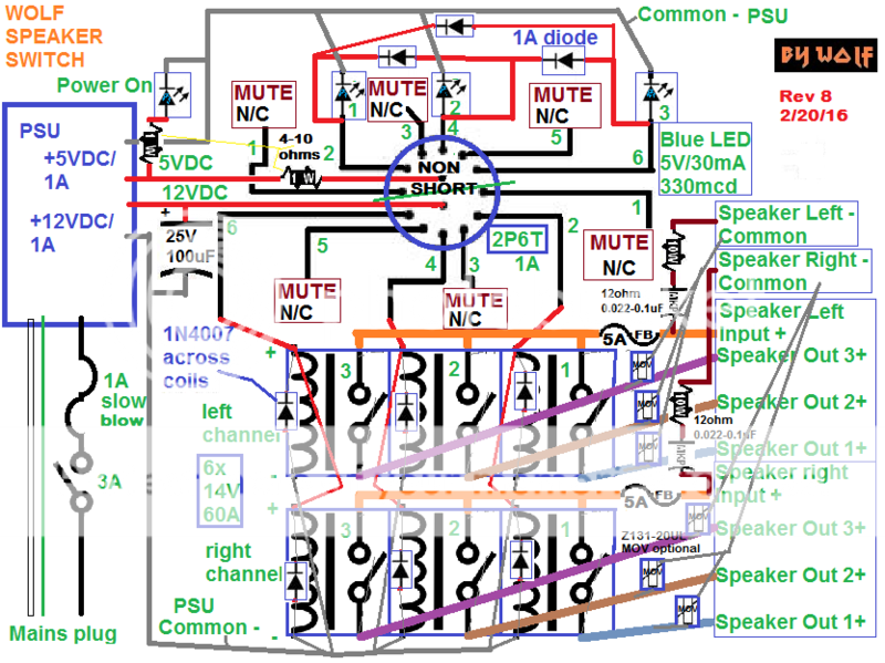
Update:
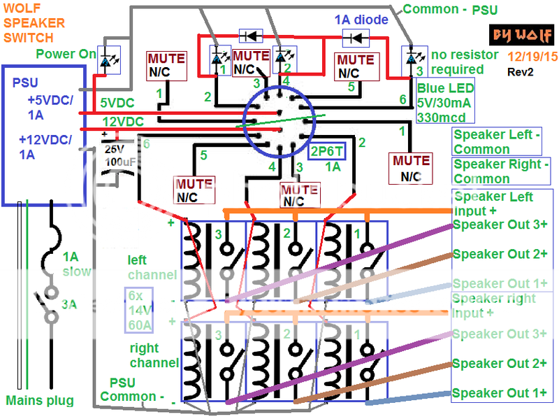
Added capacitor "to absorb energy from the relays. This might help protect the power supply, but it probably isn’t needed. Keep contact resistance low. If the coil resistance of the relays is below 75 ohms you might want to consider a beefier power supply" - Neil Davis
I still have one more opinion pending...
Wolf
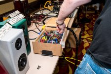
Just wanted to post where I'm at currently with this project.
I have a majority of it assembled, but no pictures yet.
Here is what is likely the final schematic:
I added the MOVs just because I have them. They won't hurt, but won't necessarily be required.
Pictures to come,
Wolf
I have a majority of it assembled, but no pictures yet.
Here is what is likely the final schematic:
An externally hosted image should be here but it was not working when we last tested it.
I added the MOVs just because I have them. They won't hurt, but won't necessarily be required.
Pictures to come,
Wolf
If I could edit the graphic above I would. I deleted the picture from the photobucket because I have the MOVs in the wrong place. Yet- it still shows up in the previous post.
Anyway- the MOV's are to be placed across the outs on the unit. IE- across each +/- speaker out terminal pair.
I'll update and repost the correct picture. Sorry for the confusion,
Wolf
EDIT:

Anyway- the MOV's are to be placed across the outs on the unit. IE- across each +/- speaker out terminal pair.
I'll update and repost the correct picture. Sorry for the confusion,
Wolf
EDIT:

Last edited:
Well- Initially, the device worked as expected. I got everything wired up this evening.
Then- the 5V LEDs started to die one by one over the course of about a half hour. I guess I might need current limiting resistors EVEN WITH the 5VDC supply. I didn't know if these 5VDC LEDs had resistance pre-added or not.
I checked the voltage at the point of the LEDs, and it still has supply at the correct voltage at each point.
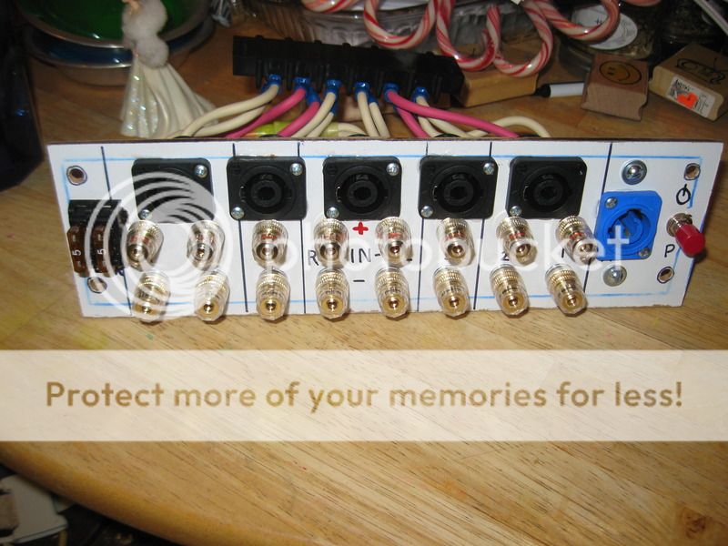
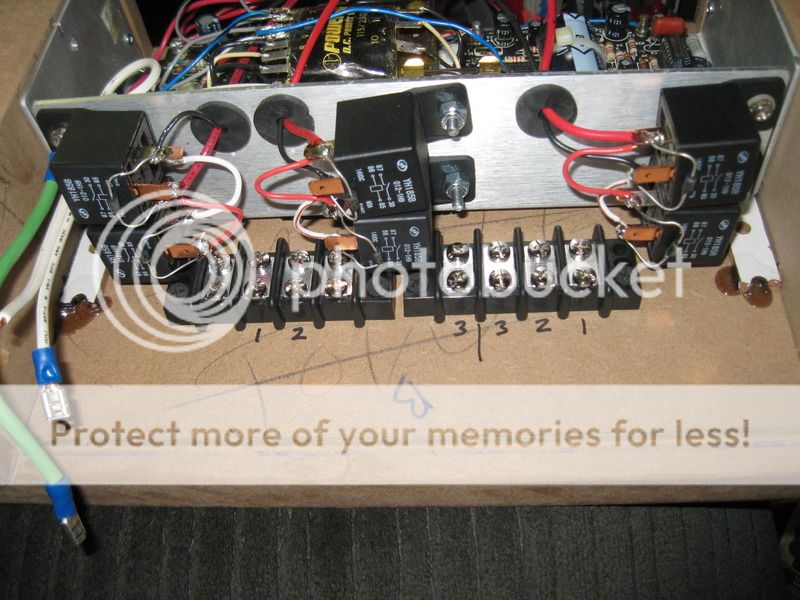
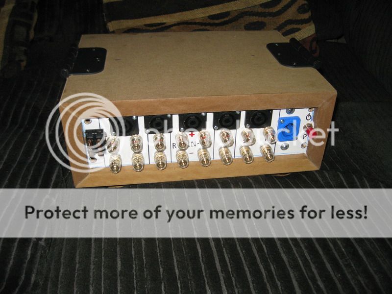
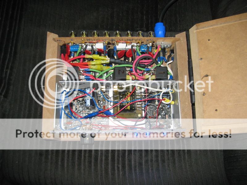
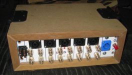
Back panel loaded:
Rear of rear plate:
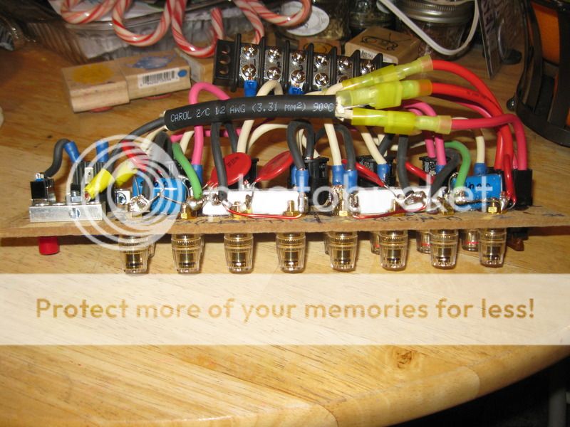
You can see the CR filters down the middle of the binding posts from the input to the negative buss. Then the MOVs are attached across the +/- binding post leads atop of the CR filters. All ins and outs are paralleled into the Speakons. Glue and screws were used in mounting virtually all components on the back panel.
Switched the 6 row to a pair of 4-circuits (only 6 are connected) to get them to fit.
Wired input side to relays, Red is right, Black is left:

Wired out outs from relays and ins from relays to the in/out board:
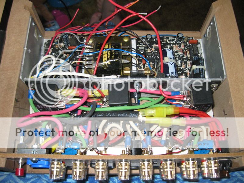
Rear panel Installed:
Wired up LEDs and switch:
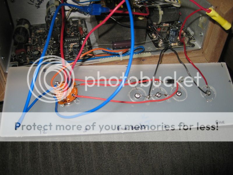
Ready to close the lid:
Here are some pics before the LEDs died...
Power:

Relay pair out 1:

Relay pair out 2:

Relay pair out 3:

Oh- and I did check that the relays worked for the right jacks. I used a voltmeter for continuity on the ins and a jumper for the outs for both channels and everything works properly.
Proper resistance for the 5V LED should be 4-10 ohms, and 60-180 for a 3.3V LED equivalent, depending on desired brightness.
Last and final updated graphic below. Resistor shown is 1W.:
Thanks for looking!
Wolf
Then- the 5V LEDs started to die one by one over the course of about a half hour. I guess I might need current limiting resistors EVEN WITH the 5VDC supply. I didn't know if these 5VDC LEDs had resistance pre-added or not.
I checked the voltage at the point of the LEDs, and it still has supply at the correct voltage at each point.
Back panel loaded:

Rear of rear plate:

You can see the CR filters down the middle of the binding posts from the input to the negative buss. Then the MOVs are attached across the +/- binding post leads atop of the CR filters. All ins and outs are paralleled into the Speakons. Glue and screws were used in mounting virtually all components on the back panel.
Switched the 6 row to a pair of 4-circuits (only 6 are connected) to get them to fit.

Wired input side to relays, Red is right, Black is left:

Wired out outs from relays and ins from relays to the in/out board:

Rear panel Installed:

Wired up LEDs and switch:

Ready to close the lid:

Here are some pics before the LEDs died...
Power:

Relay pair out 1:

Relay pair out 2:

Relay pair out 3:

Oh- and I did check that the relays worked for the right jacks. I used a voltmeter for continuity on the ins and a jumper for the outs for both channels and everything works properly.
Proper resistance for the 5V LED should be 4-10 ohms, and 60-180 for a 3.3V LED equivalent, depending on desired brightness.
Last and final updated graphic below. Resistor shown is 1W.:

Thanks for looking!
Wolf
And the final schematic:
The 3rd diode reduces the voltage drop to the 1st LED in the 3rd selection position. At most, resistance change for LED output level would be the adjustment.
And to reiterate- this is a speaker selector switch, not intended for use as a multi-amp switch. If you double up the relays and switch both + and - outputs, then this would be doable, but would require a stouter power supply.
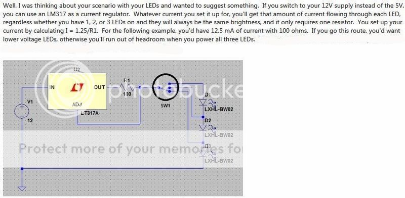
Also of note- An alternate LED arrangement that would keep them all the same output with the same bias current involves a regulator, lesser Vf LEDs, and a beefier 12VDC supply without the need for the 5VDC supply. 1100xxben on PETT offered this circuit:
Later,
Wolf

The 3rd diode reduces the voltage drop to the 1st LED in the 3rd selection position. At most, resistance change for LED output level would be the adjustment.
And to reiterate- this is a speaker selector switch, not intended for use as a multi-amp switch. If you double up the relays and switch both + and - outputs, then this would be doable, but would require a stouter power supply.
Also of note- An alternate LED arrangement that would keep them all the same output with the same bias current involves a regulator, lesser Vf LEDs, and a beefier 12VDC supply without the need for the 5VDC supply. 1100xxben on PETT offered this circuit:

Later,
Wolf
Wolf,
That is great work in constructing your switching box.
Using the LM317 voltage regulator as a current source is a great solution to lighting the LEDs evenly regardless of the number lighted. However, I'm not clear as to where the problem of different LEDs unevenly lighted derives from. A conventional schematic of the switching circuit might help.
How about switching the line level audio signals to a set of eight power amplifiers, that is four sets of stereo power amplifiers? If the output power rating of the amplifiers is not needed to be more than say 30W per channel, that might not be too costly and solves the problem of a low load to a single stereo power amp driving 4 speakers in parallel per channel.
-Pete
Wolf,
That is great work in constructing your switching box.
Using the LM317 voltage regulator as a current source is a great solution to lighting the LEDs evenly regardless of the number lighted. However, I'm not clear as to where the problem of different LEDs unevenly lighted derives from. A conventional schematic of the switching circuit might help.
How about switching the line level audio signals to a set of eight power amplifiers, that is four sets of stereo power amplifiers? If the output power rating of the amplifiers is not needed to be more than say 30W per channel, that might not be too costly and solves the problem of a low load to a single stereo power amp driving 4 speakers in parallel per channel.
-Pete
The dimmer LEDs arises from the parallel wiring I gave them, and the voltage drop across the diodes backfeeding them when a second or 3rd speaker pair is selected. In other words- it's self-induced, and how I wired them on purpose. I just did not expect it to dim as much as it did, and added the 3rd diode to minimize the effect. It's how I want it to work.
As to having 4 speakers in parallel per channel- that's not how this switch works.
Later,
Wolf
As to having 4 speakers in parallel per channel- that's not how this switch works.
Later,
Wolf
Yes, I'm sorry, after being more careful looking at your schematic diagram, I see that your box is for switching 3 pairs of speakers.
If your LEDs drop 3.4V, a 47 Ohm resistor is needed in-series with each LED for "good stability and predictable current comsumption". This according to Don Klipstein,
LEDs 101
Take Care,
Pete
I'm using 5V LEDs in mine. The resistor placement is ahead of the switch to provide current limiting for all 3.
Later,
Wolf
I'm using 5V LEDs in mine. The resistor placement is ahead of the switch to provide current limiting for all 3.
Later,
Wolf
What you are doing with the LEDs obviously works, but isn't considered good practice. Given the 5V drop of the LEDs, the supply voltage at a minimum should be 6 Volt to allow a resistor to control current through the LED. Also connecting LEDs in parallel to one series resistor is a no, no.
All of these practices are in LEDs 101. Blue LEDs deserve better treatment than that. I don't currently have any, so I'm not sure if they are still super expensive.
Regards,
Pete
I don't mind the lower voltage as they tend to be a bit bright.
Later,
Wolf
I don't mind the lower voltage as they tend to be a bit bright.
Later,
Wolf
You can lead a horse to water, but the horse will do as it pleases.
Since Photobucket went stupid, I'll repost what I ended up with.
I will also say, the 1st and second LED worked fine until I had to further attenuate the brightness. Then the 1st and 3rd were bright in 3rd engaged pair indication- so I removed the diodes. It's easy enough to see indication of 1st, 2nd, or 3rd pair.
I also used a 100 ohm 7W resistor for the current limiting, and further added a 1/4W 100kOhm potentiometer wired like a rheostat to dim the LEDs as required. Of note- I have 2 resistors shown for power indication and pair indication, but I could not picture the circuit as drawn with a single resistor. I only have one resistor ahead of all LED's installed in the piece of equipment.
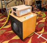
It's been used now at several DIY events without issues arising.
Just for posterity sake...
Wolf
I will also say, the 1st and second LED worked fine until I had to further attenuate the brightness. Then the 1st and 3rd were bright in 3rd engaged pair indication- so I removed the diodes. It's easy enough to see indication of 1st, 2nd, or 3rd pair.
I also used a 100 ohm 7W resistor for the current limiting, and further added a 1/4W 100kOhm potentiometer wired like a rheostat to dim the LEDs as required. Of note- I have 2 resistors shown for power indication and pair indication, but I could not picture the circuit as drawn with a single resistor. I only have one resistor ahead of all LED's installed in the piece of equipment.
It's been used now at several DIY events without issues arising.
Just for posterity sake...
Wolf
Attachments
Last edited:
- Status
- This old topic is closed. If you want to reopen this topic, contact a moderator using the "Report Post" button.
- Home
- Loudspeakers
- Multi-Way
- speaker selector switch