OK I mostly finished one of my cabinets... I haven't put the chamfer on the baffle yet as I don't have the veneer, and the back is only being held on with strap clamps, but it seems ok....
I did acoustic measurements and my MW144's performance is looking far from good. They are really smooth on a nearfield measurement up to about 1Khz, but when I measure onaxis at about 85cm they are realy bad.
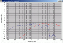
I managed to do some simulation in speaker workshop and found that a second order LR crossover on the woofer at about 1Khz, with a 2nd order LR on the tweeter at about 2.2Khz + and lpad at about 4.5db cut gave something aproaching a smooth response, almost completely compensating for baffle step (probably too much so!).... but what is really bugging me is that the MW144 should be much smoother than this, and I can't work out why it has a massive dip at 2.3Khz and then lower response from about 3Khz to 5Khz.... It sort of corresponds to simulations in BDS (as far as the curve shape is concerned) but the magnitude is much greater! BDS shows a dip of about 3db at 2300Hz but I'm, getting about 12db!! also BDS only shows about 1db difference between the trough and the frequencies from 3Khz on, but I have 3db.....
The attached pic shows the woofer repsonse + tweeter response (in red).... I think based on the fact that the tweeter isn't showing big dips at 2.3K I can rule out my mic as being dodgy (though I still may try another wand...)
I've tryed lining the walls with foam, and putting in polyester stuffing, this had no effect on the dip at 2.3Khz, but did remove a nasty peak (of about 6db) at 5Khz.....
Should I beleive the results I'm seeing and design my crossover with that, or should I try and get to the bottom of why I have such a large dip???
Is it likely that this is the actual response of my drivers?? or some other factor like standing waves or baffle diffraction.
Tony.
Attachments
I'm not familiar with the driver but where are you measuring.... in line with the tweeter.... between tweeter and woofer.... is the measuring distance a bit close.... only thoughts.
Maybe the dip on the woofer is the transition from the cone to the dust cap.
What's it sound like with music?
No help but just thinking out aloud.
Maybe the dip on the woofer is the transition from the cone to the dust cap.
What's it sound like with music?
No help but just thinking out aloud.
Hi Inertial,
I have got a flare internaly, used a 15mm chamfer bit.... but maybe the mounting hole is too tight before the flare... Your English is fine by the way
Hi Rabittz,
measuring in line with the tweeter.... distance was 87cm, tried this afternoon at about 2M and got the same result. It is an mtm and both woofers were running, but If I disconect one, same story.
I did a very makeshift crossover 1st order, just stock components for 3Khz without any impedance compensation. Some vocals sound great (Jeniffer warns) some sound crap (Nick Cave)..... reversing the tweeter polarity helps with nick cave but the measured response is awfull with a huge dip (about 20db) at both 2Khz and 20Khz... The weird thing was, that it sounds better with the mw144 running full range, no coil, than it does with the coil.
I went back and looked at some of my tests, and I tested on the baffle only no box, and had the same dip so I can rule out the box could be the baffle though.....
The graph I have seen is from morel europe and it shows it being pretty flat out to 7Khz and then drops just like my graph does at 5Khz...... me thinks they fudged it
Looks like I got more than I bargained for, this was supposed to be an easy driver for me to do a crossover for. I thought if it is flat to 7Khz the crossover will be a lot easier (since it's my first one)....
attached is a picture of the rear of the baffles.
Tony.
I have got a flare internaly, used a 15mm chamfer bit.... but maybe the mounting hole is too tight before the flare... Your English is fine by the way
Hi Rabittz,
measuring in line with the tweeter.... distance was 87cm, tried this afternoon at about 2M and got the same result. It is an mtm and both woofers were running, but If I disconect one, same story.
I did a very makeshift crossover 1st order, just stock components for 3Khz without any impedance compensation. Some vocals sound great (Jeniffer warns) some sound crap (Nick Cave)..... reversing the tweeter polarity helps with nick cave but the measured response is awfull with a huge dip (about 20db) at both 2Khz and 20Khz... The weird thing was, that it sounds better with the mw144 running full range, no coil, than it does with the coil.
I went back and looked at some of my tests, and I tested on the baffle only no box, and had the same dip so I can rule out the box
The graph I have seen is from morel europe and it shows it being pretty flat out to 7Khz and then drops just like my graph does at 5Khz...... me thinks they fudged it
Looks like I got more than I bargained for, this was supposed to be an easy driver for me to do a crossover for. I thought if it is flat to 7Khz the crossover will be a lot easier (since it's my first one)....
attached is a picture of the rear of the baffles.
Tony.
Attachments
wintermute said:The weird thing was, that it sounds better with the mw144 running full range, no coil, than it does with the coil.
I usually run most of my mid woofers almost full range (driver dependant of course) and cross over to the tweeter with a 1st order series. Maybe a different crossover point. What can work extremely well is different orders on the drivers such as 1st on the woofer and 2nd on the tweeter to achieve the desired acoustic roll off.
Does the Morel graph have any little bumps or blips in the impedance plot between 2000Hz-3000Hz and is there any on your measured impedance plot? Could indicate the source of the dip is the driver.
It's all fun isn't it..... good luck with it.
Hi guys,
I had been considering using felt like duntech, and decided not to offset the drivers based on the info on their site... I bought some felt but it is too thin to have any effect, need to find some that is about 5mm thick...
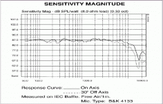
The response plot I have is from eltimaudio which I think is morel's european distributor.... Morel Isreal have very limited info available on their web site. The curve has very little resemblence to my drivers, and is I think Highly suspect.... the low end goes way too low, and the high end is too extended... atached is a copy of the response plot.
It does have a dip at about 2600 or so... but I don't have anything like the response curve for my nearfield measurements, mine are much smoother...
I'm thinking if I can get rid of the 2.3K dip, I might be able to put in a wide notch filter to bring the hump between 800 and 1800 Hz down but I can play with that in sims and see how it goes
Thanks for the tips rabbitz and inertial, I'll keep at it, though I have a few other priorities I need to get out of the way first!
Let the fun begin
Tony.
Attachments
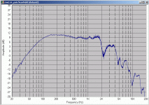
Here is a nearfield plot, note I still have a problem with my mic, giving lots of little ripples.... need to get to the bottom of that.
Irregularities between 500Hz and about 1.5Khz are damped internal reflections or standing waves. much worse without damping material
Tony.
Irregularities between 500Hz and about 1.5Khz are damped internal reflections or standing waves. much worse without damping material
Tony.
Attachments
Hi Tony,
Not only amps, speakers too huh...
Your graph looks pretty normal, doesn't seem that there are any problems with the mic. The dip looks like its caused by cone breakup, which is pretty much material-dependent. Of course there's the question as to why the manufacturer's curve doesn't look the same... well, possibly:
1. The measurements are pretty much smoothened usually, at least 1/3 octave or more.
2. The materials used on the woofer then (versus now) is a bit different. I'm not familiar with the woofer in question, but it wouldn't be surprising to find differences in material characteristic (specially if the woofer is pulp).
3. You would't be overloading the mic preamp (or mic itself) would you? (though am not sure what the effect of such would be)
MTMs are better worked with 3rd octave crossovers, if I recall properly. In this case you may have to consider using a different woofer (oops) or moving the crossover frequency down. A 2nd order LPF coupled with a 3rd order unit for the tweeter may come out better...
Cheers!
Hi Clem  yeah I was only playing with the amp as a break from the speakers
The cone material is damped polymer composite..... I might try taking a measurement not mounted in a baffle (just sitting on the floor) and see if the dip is still there, obviously if it is then it's the speaker itself
you are correct, Joe d'appolito used 3rd order butterworth in his initial designs, but later started using 4th order linkwitz riley, when I simulated with 2nd order LR, the actual rollof was pretty much 4th order LR, so I was thinking that would probably work ok....
for the gated measurements, I don't think there is any chance of mic or preamp overload, for the nearfield measurement however, I suspsect one or other was overloading, as it is more noisy than I normally get, will have to do another one.
Tony.
Looks like the damping of the polymer disappeared huh... 
Regarding the amplitude rolloff - I am wondering about the phase response in the crossover region: it may look like its 4th order due to the aggregate rolloffs of the xover network and the driver natural response, but what about the phase relationship? You may get a dippy-lumpy vertical polar response in the xover frequency region...
Cheers!
hmmmm now you are getting technical  The drivers are time aligned so I'm hoping not to have any phase issues.... but SW should do a fairly good job of simulating it, and if there are problems they will hopefully show up in the simulation.
I noticed another thread a while back about using an Audigy II ZS for corossover prototyping, I'm going to have to dig that up, as it will be a lot easier (and cheaper) than making up multiple crossovers and seeing how they sound... will only be able to test a single speaker, but that will be ok
just setting up for a nearfield test of a midbass sitting on the floor
Tony.
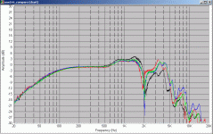
I know you aren't supposed to use nearfield measurements for freqencies above 200-300Hz, but I think that these results show that the issue is with the drivers themselves 
though at least the dip is a very sharp one, so maybe won't be too bad..... I tested all four mw144's sitting on the floor, no box, nearfield, the attached graph shows all four.
the dip is at 2000Hz as opposed to 2300, but that is probably due to the fact that the cone doesn't have the extra loading that the sealed box gives....
Tony.
Attachments
Hi Tony,
Does the simulation include off-axis modeling? The on-axis response will probably look good, but the off-axis response at the crossover region could look pretty lumpy (this is what I was referring to in my previous post)...
About the dip in response - that wouldn't be the floor reflection cancelling out the response of the driver? Just curious - are you taking your measurements with the drivers in free-space (i.e. suspended)?
oops - you mentioned you have it on the floor....
Cheers!
I guess it is possible, maybe I should rig it in free air and test again  though the length of a wavelength at 2000Hz is about 175mm which is much greater than the distance between the back of the driver and the floor....
not sure if it includes off axis modelling, I have 30 and 60 degree off axis measurements so It possibly will let me use them.... I can always look at some other simulation packages too.... and I guess I can always use the listen and tweak approach
These drivers are 5" btw.
Tony.
not sure if it includes off axis modelling, I have 30 and 60 degree off axis measurements so It possibly will let me use them.... I can always look at some other simulation packages too.... and I guess I can always use the listen and tweak approach
These drivers are 5" btw.
Tony.
Could really be the drivers. I remember I was working on Vifa units of about the same size, arranged in the same MTM config. Didn't have that funny dip (I use Laud to do my frequency response tests), and wound up crossing at about 2+KHz, into a Scanspeak tweeter, although the arrangement used an electronic 3rd order crossover.
Cheers!
Cheers!
There is one think that is bugging me.... I did a lot of tests here at home and kept getting awfull looking results, especially on the tweeter.... I did one test and got an almost perfect looking curve on the tweeter, no more than +- 1db from 2000 to 15000 Hz, then SW crashed, and I hadn't saved..... I have never been able to repeat it.... that one measurement that looked as it should has always made me doubt my other measurements.....
I emailed the distributor and he reckons it is measurement errors.....
He did say that there was a very small posibility that electrical loading of the driver could be causing it, I guess my amp comes into question again on that one
One thing I thought of this morning, is that maybe I should do a test with the bottom gate moved up to the start of the pulse.... I figured that it is possible that because there are multiple samples, that the 5ms or so before the pulse starts is recording reflections from the previous sample, and stuffing up the curve...
something for me to look at next week I think
Tony.
Hi Tony - If your software can, perhaps you should be looking at the time-domain pulse response. Or, perhaps the simplest test will be to get a 'really good' driver and have a look, sort of a sanity check for the testing instrument... Somehow I would really doubt that 'electrical loading of the driver' could cause such problems. A crossover network will introduce a lot more impedance funnies than any solid-state amp would...
Cheers!
Cheers!
Hi Clem
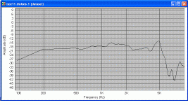
I just went looking for some pulse response plots, and came across this old measurement I did. Seems that I might well have an issue with my measurements (probably with the environment). This one to me looks a lot better than the recent ones.
I think that I have not been able to sucessfully get rid of floor reflections, and I'm limited to what height I can place the speaker, so it is possible I'm getting some nasty reflections that I can't eliminate from my measurements. I'd say that the peak at 5HKhz is real, and I'll probably need a notch filter on that, and I'd also say that the hump at 1Khz is real.... this curve actually looks very like the one from the baffle diffraction simulator...
This one is on the old prototype which has a different baflfle, but the later tests on this box were pretty much the same as the latest final box.
Tony.
Attachments
- Status
- This old topic is closed. If you want to reopen this topic, contact a moderator using the "Report Post" button.
- Home
- Loudspeakers
- Multi-Way
- crossover design... suspect data??
