Please can any one clarify the following doubts?
Given a constant box volume, is the resonant frequency of a speaker in that box independent of its free-air resonance? That is, if we have three speakers with different Fs, would all these three speakers have the same in-box resonance frequency in the box?
My sound card (SB16) shows a difference of 30mV between 30Hz and 50Hz -- the output voltage is fairly constant (within a couple of millivolts) after 150Hz. Is there a way I can obtain constant voltage output from 20Hz onwards?
Please help.
Hi r_s_dhar
Could you please explain what you are doing or intend to do ?
Are you doing TS-parameter measurements ?
If yes, how does your measurement setup look like ?
Regards
Charles
P.S. The in-box resonance is of course not the same for the combination of the same box but different drivers.
Could you please explain what you are doing or intend to do ?
Are you doing TS-parameter measurements ?
If yes, how does your measurement setup look like ?
Regards
Charles
P.S. The in-box resonance is of course not the same for the combination of the same box but different drivers.
Hello Accurate,
I casually browsed through some 1950s books while doing TS tests on my woofers. As you know, most of these older books have nomograms for designing bass reflex enclosures, depending entirely on the Fs of the speaker. But in the simulation programmes that we have now, Fs is not important, while Qms, Qes and Vas are. I also glanced through an older article by some Ausberger or so (I dont remember the exact name now) on double chamber bass reflex enclosure in which he fits three dissimilar speakers in his test box to show that, irrespective of the Fs of these speakers, all of them have the same closed box resonance.
Now I was just wondering whether the closed box resonance (system resonance or F3) is entirely the function of the box volume.
Hi r_s_dhar,
Actually, there was a whole series of papers by Small covering the complete analysis of Direct Radiating Loudspeakers in the AESJ (I'm sure Phase_Accurate knew this, he was just being brief). The last I looked, the whole series + other articles from the AES Journals were obtainable from Old Colony Sound at this link:
http://www.audioxpress.com/index.htm
I'm not sure what their shipping policies are, but you can find out there.
Happy hunting,
Rodd Yamas***a
Dhar:
In a reflex box, the resonant frequency of speaker is whatever the box is tuned to. This is known as Fb.
That doesn't mean that the response will be 3 dB down at that point. The response could be anything from above the midpoint down to 24 dB down or more. That is a separate question. But the resonance will be whatever the box is tuned to. It will also be the point of lowest impedance located between to humps of very high impedance, if you want to check.
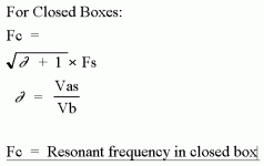
For closed boxes, the resonance frequency, (Fc) is definitely affected by, but not identical to, the Free Air Resonance Frequency, (Fs).
The box below gives the formula to find the Closed Box Resonance Frequency, (Fc). This website does not allow Microsoft Equation Editor in the text portion.
Again, remember that in the Closed Box as well as the Bass Reflex, the response will NOT necessarily be 3 dB down at the Resonance Frequency. In fact, in the Closed Box, the response will only be 3 dB down if Fc equals .7. If Fc is below .7, the response will be more than 3 dB down. If Fc is above .7, the response will be higher than -3 dB.
In a reflex box, the resonant frequency of speaker is whatever the box is tuned to. This is known as Fb.
That doesn't mean that the response will be 3 dB down at that point. The response could be anything from above the midpoint down to 24 dB down or more. That is a separate question. But the resonance will be whatever the box is tuned to. It will also be the point of lowest impedance located between to humps of very high impedance, if you want to check.
For closed boxes, the resonance frequency, (Fc) is definitely affected by, but not identical to, the Free Air Resonance Frequency, (Fs).
The box below gives the formula to find the Closed Box Resonance Frequency, (Fc). This website does not allow Microsoft Equation Editor in the text portion.
Again, remember that in the Closed Box as well as the Bass Reflex, the response will NOT necessarily be 3 dB down at the Resonance Frequency. In fact, in the Closed Box, the response will only be 3 dB down if Fc equals .7. If Fc is below .7, the response will be more than 3 dB down. If Fc is above .7, the response will be higher than -3 dB.
Attachments
Go to www.diysubwoofers.org and you will find equations for many different types of boxes. Reading all of that old pre T/S literature is just confusing because many of the people who wrote it were just fumbling around for a rule of thumb that would help them design more acceptable boxes.
Useful information on bass design didn't start being published in the US until almost 1971, when Nevile Thiele's 1961 article was reprinted in the JAES. Novak and some of the others you are probably reading established some of the fundamentals, but it wasn't really all brought together until Thiele, Small and little mentioned Benson.
Benson's book "Theory and Design of Loudspeaker Enclosures" (actually a series of papers) is available from www.audioxpress.com, but it requires some fairly advanced math (circuit analysis and LaPlace Transform techniques) to get anything out of it.
Ron:
I did not know that Neville Thiele originally published his article in 1961, and it only was republished in the Journal of the Audio Engineering Society in 1971. That would explain a lot.
I must disagree with you about Robert Novak, though. No fumbler he. At least not by 1955. That was the year he published this short article in the Journal of the Audio Engineering Society about building closed boxes and reflex boxes.
By 1955, audio engineers pretty much had the closed box figured out. However, the ported box was full of conjecture with many different theories abounding. According to author David Weems, conflicting theories such as "Tune to the free air resonance" had it's adherents, as did the contradiction, "Free air resonance means nothing". And so forth.
Novak simply showed how to use the parameters already used in the closed box and apply them to the ported box. He used as an example what would later be labelled by Thiele as the "Classic alignment" where the Qts of the speaker was .383.
In that article, Novak basically had the reflex box solved. He had a chart which showed some variations the designer could expect as well. It really was all a designer really needed to build a good ported box with flat response, and most ported designs made can be explained by that article.
Thiele's later article was in every way much more detailed, and included designs useful only if equalization was included, which Novak's simple article did not. I do not disagree with your contention that the reprinting of Thiele's article kicked off the immense popularity of the reflex box. Before that article, reflex designs were considered kind of a "boom box" useful only for those who wanted artificially high bass.
It is good that Weems gives credit to Novak, for without Weems' mention, Novak would appear to be almost forgotten.
Thiele's article was much more detailed, but Novak had the vented box figured out in 1955.
Gentlemen,
I don't know all there is to know on the history of the study of acoustics and particularly, loudspeakers, but there are at least two others on which the work by Thiele, Small, Benson, and Novak are based. I mention these two because I know of them, and they deserve at least mention in a discussion such as this.
Harry F. Olson is one of the pioneers in the field of acoustics. Most of the papers written on acoustics, or loudspeakers in the past four decades lead back to the work of Olson.
Leo L.Beranek whos book on acoustics was published in 1954. It covers the electrical equivilant circuit of drivers in free air, infinite baffles, closed boxes, vented boxes, and horns. It includes methods for filter analysis and parameter relationships that serves as the basis for more complete analysis by more recent researchers such as the ones mentioned and others.
If interested, the book is Acoustics
Leo L. Beranek
McGraw-Hill, Copyright 1954.
It may still be available as one of the McGraw-Hill Electrical and Electronic Engineering Series.
Rodd Yamas***a
Roddy:
I don't know all there is to know about the subject either. However, what reading I have done says you are correct. Most of the early articles based their work on Beranek and Olson.
In addition, most of the crossover design seems based on a book by a fellow named Weinberg.
Olson apparently also did a lot of important research in radio design. In addition, he was the inventor of the Drone Cone, which somehow got switched to being called the Passive Radiator. Frankly, I much prefer Olson's name for his own invention.")
I don't know all there is to know about the subject either. However, what reading I have done says you are correct. Most of the early articles based their work on Beranek and Olson.
In addition, most of the crossover design seems based on a book by a fellow named Weinberg.
Olson apparently also did a lot of important research in radio design. In addition, he was the inventor of the Drone Cone, which somehow got switched to being called the Passive Radiator. Frankly, I much prefer Olson's name for his own invention.
Beranek and Novak solved the equivalent circuit and made some general theoretical comments.
I believe Thiele was one of the first to apply many "alignments" to the circuit theory (Novak mentions Butterworth) and he established methods for measuring combination parameters useful for design. Neville Thiele and those who follow (Benson, Small, Fincham, Geddes....) provide the information most useful to hobbyists. Vance Dickason in his loudspeaker Cookbook boils it down to a level high school kids can understand, and Weems brings it down to a level that junior high kids can probably manage
Beranek and Olson are useful books to have on the shelf if you are delving deeply into the theory and are at an undergraduate-graduate level of engineering and know complex math and circuit analysis. Benson's book is probably far more valuable as a start because it has an extensive bibliography that lets you know what he is getting from the eaarlier authors. He duplicates their results with his general theory and so proves it useful and comprehensive. Little of this is practical to the hobbyist, unless s/he be quite advanced, which rs_dhar does not seem to be.
Ron E said:Beranek and Olson are useful books to have on the shelf if you are delving deeply into the theory and are at an undergraduate-graduate level of engineering and know complex math and circuit analysis.
Olson's book is worth having just to look at the pictures.
The math in these 2 books is somewhat intimidating and i say that having an honours BSc in math (although i have forgotten most of it).
dave
Beranek, in his section on closed box loudspeakers, solved and graphed the normalized response of a closed box loudspeaker for Qt = 0.1 to 10 in 7 steps for normalized frequencies from 0.1f3 to 10f3. Can you imagine how long that took with a slide-rule back in the early 50's. It boggles the mind.Beranek and Novak solved the equivalent circuit and made some general theoretical comments.
Rodd Yamas***a
All Elders and Peers,
Thanks for your remarks. I have actually completed TS tests on my woofers and midranges and shall put the results on this string to ask you whether the figures look acceptable. In the Meanwhile I have problems with the formula to arrive at Vb. Actually there are two different formulae and they give me results varying the volume by almost 1 cubic feet. The first formula is:
Vas = Vb((Fb/Fs)2-1)
found in http://sound.westhost.com/tsp.htm
The second one is:
Fc*Qec
Vas = Vb [ -------- - 1 ]
Fs*Qes
found in http://www.crackinguniversity2000.it/Panorama/documents/audio/speaker_parameters.html.
Phase_Accurate,
I have quite a few freeware programmes to simulate. But the one I feel at home with is PET149, DOS based.
A part of my original question hasn't been still answered. Are there programmes which can correct the frequency response characteristics of the amp chip on the soundcard and provide as flat as possible signal from 20Hz onwards?
Thanks again.
The first equation is for designing boxes, the second is for measuring parameters.
As for correcting the response of your soundcard, there is nothing you can do. If you recalibrate your T/S setup for each frequency in that range, you will cancel out the effects of the soundcard and/or your meter (many meters roll off below ~40 and above 1kHz).
As for correcting the response of your soundcard, there is nothing you can do. If you recalibrate your T/S setup for each frequency in that range, you will cancel out the effects of the soundcard and/or your meter (many meters roll off below ~40 and above 1kHz).
Ron,
You are right. I am not advanced, but I want to go as far as I can. I am basically a university teacher with a PhD in English Literature. My interest in classical music has (mis)led me into electronics. There was a time when I thought all I had to do was to buy one of those Japanese HiFi Decks. I got an opportunity to play my collections on a pricey music set -- the result was disappointing. It was then that an engineer friend of mine told me that I should build my own set if I wanted dedicated performance. I have covered a considerable distance since then, but then I have "miles to go before I sleep."
I am not satisfied in just filling in blanks and getting results from computer programmes. I want to know what and why I am doing something. At present I am building a dedicated millivoltmeter to do my TS tests. My present problem is that although I understand the TS equations in general, I do not see how inidividual Q elements determine the Vb and SPL. I have tried one simple method of varying these factors in simulations to see how the curve comes out. But that is a blind method.
Thanks.
r_s_dhar,
The various Q factors are numbers that represent the relationships between various physical parameters of the driver, the box, or the driver in the box. It's the physical parameters that determine the value of the various Q factors.
If you have a given driver, all of your driver Q's are set. You can only alter the parameters of the box and in that way the total Q of the system.
You need to obtain some of the papers from the 70's to get clearer understanding of how the relationships between the parameters form the various Q factors.
Try back tomorrow, I might be able to set something up to get some more substantial information to you. In the interim, try some web searches on the Thiele and Small parameters.
Rodd Yamas***a
- Status
- This old topic is closed. If you want to reopen this topic, contact a moderator using the "Report Post" button.
- Home
- Loudspeakers
- Multi-Way
- Enclosure Volume