Hi all ")
I am starting a new 2-way speaker project and the initial plan was a classic 15" + horn/waveguide. Passive crossover approx. 700/800hz.
It's been my experience that the transition between horn and a direct radiator can be problematic, it sounds a bit disconnected between the two.
I read somewhere, maybe on this forum, that the radiating surfaces should be close in size to provide a better horizontal directivity match.
So if I used a mid-horn with a bigger mouth size compared to the Sd of the direct radiator, this may be the culprit.
So I started thinking about the classic studiomonitors where they would use two 15" drivers in a side by side configuration with a radial horn above.
Thoughts about this, does this approach give a better directivity match between direct radiator and horn?
Hi Rob, stacking vertically will not be possible with a 2-way design. I would need to cross the lower woofer at a much lower frequency (max 200hz) to avoid serious lobing because of the greater distance to the mid horn.
This would require a 2.5 way design, or D'appolito configuration. It would also not provide greater horizontal dispersion.
This would require a 2.5 way design, or D'appolito configuration. It would also not provide greater horizontal dispersion.
Last edited:
Good point Dmitrij, but I know these large studiomonitors are crossed over an octave higher than that.Side by side 15" woofer configuration requires quote low crossover frequency (300-400Hz) to avoid lobing problems (in horizontal plane) and discontinuity of the directivity index at the crossover frequency.
As I understand, for two sources to act as one, the center to center distance between them should be no greater than 1/4 wavelength at the crossover frequency. So, like you are saying, this would be just over 200hz for two 15" side by side. I have seen some stretching this rule to 1/2W and even 1W.
Indeed many a studio monitor was built with side-by-side 12s or 15s. I've heard both good and OK. At the crossover frequencies the woofer pattern should be vertical.
What has worked best and sounded the most natural for me over the years is a woofer and horn mouth of approximately the same size. This came together best in the Altec A5 where the short front horn of the woofer was the same size as the large mid horn.
What has worked best and sounded the most natural for me over the years is a woofer and horn mouth of approximately the same size. This came together best in the Altec A5 where the short front horn of the woofer was the same size as the large mid horn.
Good point Dmitrij, but I know these large studiomonitors are crossed over an octave higher than that.
As I understand, for two sources to act as one, the center to center distance between them should be no greater than 1/4 wavelength at the crossover frequency. So, like you are saying, this would be just over 200hz for two 15" side by side. I have seen some stretching this rule to 1/2W and even 1W.
I have modeled 2x15" side by side configuration several years ago. Here is couple videos of SPL radiation pattern ant polar response
Radiation pattern
2x15 inch loudspeaker radiation pattern - YouTube
Polar response
2x15 inch loudspeaker radiation polar response - YouTube
There is no significant side lobes up to 450-500Hz but directivity index (at least in horizontal plane, vertical plane would be probably ok) would be quite high compared to that of any horn.
Last edited:
As a result of a sided bafle step effect it has to see with the cabinet sided walls size where the woofer are?
While the 4Pi to 2Pi transition is progressive, my limited experience is till 150 hz circa you can not locate the bass and what is below, certzainly because below the shroeder frequency of most rooms. My everyday main loudspeaker has a sealed firering at the rear of the loudspeaker towards the front wall (and yes it sounds good). A 15" face to face on the front/rear instead the sides is maybe doable ? I don't know....
While the 4Pi to 2Pi transition is progressive, my limited experience is till 150 hz circa you can not locate the bass and what is below, certzainly because below the shroeder frequency of most rooms. My everyday main loudspeaker has a sealed firering at the rear of the loudspeaker towards the front wall (and yes it sounds good). A 15" face to face on the front/rear instead the sides is maybe doable ? I don't know....
Thank you, this is very interesting stuff!
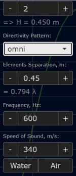
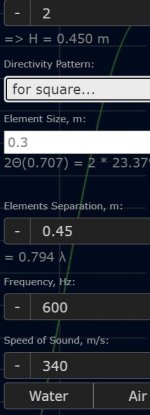
What is the difference between omni and square directivity pattern?
Attachments
Indeed many a studio monitor was built with side-by-side 12s or 15s. I've heard both good and OK. At the crossover frequencies the woofer pattern should be vertical.
What has worked best and sounded the most natural for me over the years is a woofer and horn mouth of approximately the same size. This came together best in the Altec A5 where the short front horn of the woofer was the same size as the large mid horn.
This has been exactly my experience as well Pano.
I tried Altec 1505's over Peavey FH1 folded horns, and also over a direct radiator 15". 1505 + FH1 sounded much more coherent and seamless than 1505 + DR. I suspect this is, like you mention, because the radiation area is very close in size between 1505 mouth and FH1 mouth.
I'm not sure I understand what you mean by "At the crossover frequencies the woofer pattern should be vertical." ?
I have modeled 2x15" side by side configuration several years ago. Here is couple videos of SPL radiation pattern ant polar response
Radiation pattern
2x15 inch loudspeaker radiation pattern - YouTube
Polar response
2x15 inch loudspeaker radiation polar response - YouTube
There is no significant side lobes up to 450-500Hz but directivity index (at least in horizontal plane, vertical plane would be probably ok) would be quite high compared to that of any horn.
Very nice to see this in effect, particularly the polar response!
What simulation software are you using?
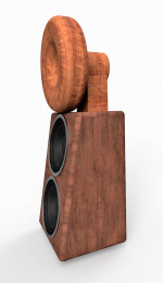
There are some solutions where the front baffle is not flat:
WARP
Some Augspurgers are also like that.
Regards
Charles
Yes I have also seen this angled front approach, very elegant solution to reduce the lobing effects.
Audiokinesis have two vertically stacked 15" woofers on a 10 degree angled baffle on their latest flagship speaker, also to reduce the lobing. This may be the easiest way to incorporate two 15" in a 2-way design. It also has the benefit of reducing the effect of floor bounce cancellation.
Attachments
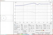
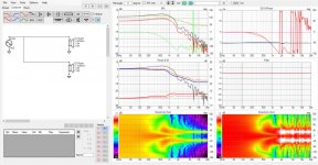
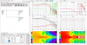
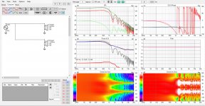
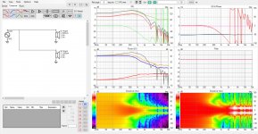
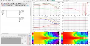
Quickie on VituixCAD, two 15" simmed on 80cm x 40cm baffle side by side.
Polar map on right is normalized, left not normalized. Not sure how well this would reflect reality.
My opinion of such setup: I see no point, the narrowing of polar is only about for one octave 300-600Hz and then there are problems above 600Hz (lobing) making it hard to integrate with a waveguide above. Maybe lobing is not that audible here below 1000kHz? Toe in reduces the lobing but turns the system into a lazer beam. But now you would need huge horn to integrate into system like this, maybe you have one. It looks like the toe in can adjust the beamwidth to better suite the horn.
The extra SPL would be more advantageous effect of two driver setup than the effect in polar I think, and in home audio we don't need the extra SPL so it feels wasted effort to me. Would look cool though, impress everyone with the looks and justify high end price tag
Attachments
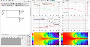
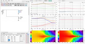
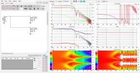
1. measurement by diffraction sim
2. single driver for reference
3. two drivers side by side flat
4. two drivers, toed in 15 deg
5. two drivers, toed in 30 deg
6. two drivers, toed in 60 deg
7. two drivers, toed out 15 deg
8. two drivers, toed out 30 deg
9. two drivers, toed out 60 deg
edit. oops, error on the attachments, used the "right" driver sim for both drivers well, error seems to be rather small so won't bother making new images. This is easy test to try by anyone, few minutes!
Polar map on right is normalized, left not normalized. Not sure how well this would reflect reality.
My opinion of such setup: I see no point, the narrowing of polar is only about for one octave 300-600Hz and then there are problems above 600Hz (lobing) making it hard to integrate with a waveguide above. Maybe lobing is not that audible here below 1000kHz? Toe in reduces the lobing but turns the system into a lazer beam. But now you would need huge horn to integrate into system like this, maybe you have one. It looks like the toe in can adjust the beamwidth to better suite the horn.
The extra SPL would be more advantageous effect of two driver setup than the effect in polar I think, and in home audio we don't need the extra SPL so it feels wasted effort to me. Would look cool though, impress everyone with the looks and justify high end price tag
Attachments
1. measurement by diffraction sim
2. single driver for reference
3. two drivers side by side flat
4. two drivers, toed in 15 deg
5. two drivers, toed in 30 deg
6. two drivers, toed in 60 deg
7. two drivers, toed out 15 deg
8. two drivers, toed out 30 deg
9. two drivers, toed out 60 deg
edit. oops, error on the attachments, used the "right" driver sim for both drivers
well, error seems to be rather small so won't bother making new images. This is easy test to try by anyone, few minutes!Attachments
Last edited:
Very nice to see this in effect, particularly the polar response!
What simulation software are you using?
It is ABEC3 (Akabak).
pelanj, by adjusting R parameter in the driver coordinates in the main program crossover window. It rotates the whole driver response set in relation to reference axis so the output is not exactly what would happen in reality (only portion of the baffle is rotated not the whole thing, and the other driver and baffle would be there to obstruct physically and cause extra interference).
Someone would need to build and measure a real proto, or do more elaborate BEM sim for more accurate results. I suspect all the reflections, with toed in drivers from each other, could somewhat average out the lobing and make the response even more wild looking overall. This setup is something I wouldn't want to do for home hifi by the looks of simulated response, but I haven't ever heard such system so take my writings as opinion.
Someone would need to build and measure a real proto, or do more elaborate BEM sim for more accurate results. I suspect all the reflections, with toed in drivers from each other, could somewhat average out the lobing and make the response even more wild looking overall. This setup is something I wouldn't want to do for home hifi by the looks of simulated response, but I haven't ever heard such system so take my writings as opinion.
Last edited:
Quickie on VituixCAD, two 15" simmed on 80cm x 40cm baffle side by side.
Polar map on right is normalized, left not normalized. Not sure how well this would reflect reality.
My opinion of such setup: I see no point, the narrowing of polar is only about for one octave 300-600Hz and then there are problems above 600Hz (lobing) making it hard to integrate with a waveguide above. Maybe lobing is not that audible here below 1000kHz? Toe in reduces the lobing but turns the system into a lazer beam. But now you would need huge horn to integrate into system like this, maybe you have one. It looks like the toe in can adjust the beamwidth to better suite the horn.
The extra SPL would be more advantageous effect of two driver setup than the effect in polar I think, and in home audio we don't need the extra SPL so it feels wasted effort to me. Would look cool though, impress everyone with the looks and justify high end price tag
Attachments
1. measurement by diffraction sim
2. single driver for reference
3. two drivers side by side flat
4. two drivers, toed in 15 deg
5. two drivers, toed in 30 deg
6. two drivers, toed in 60 deg
7. two drivers, toed out 15 deg
8. two drivers, toed out 30 deg
9. two drivers, toed out 60 deg
edit. oops, error on the attachments, used the "right" driver sim for both drivers
Amazing software you have developed here tmuikku! I have to spend more time with Vituixcad to understand it better.
And I agree with your statement that, based on these simulations it doesn't seem to be worth it using two 15" drivers side by side. No gains to be had in directivity, only extra issues.
- Home
- Loudspeakers
- Multi-Way
- Directivity of side by side woofers