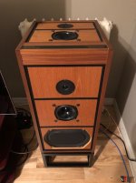
I am looking for an URL, where are to find images concerning the disassembly procedure (how I open a not screwed version of this loudspeaker for repair/upgrade resp. remove the integrated crossover network boards and replace the internal KEF B139).
The version without integrated crossover network boards (active version) works mostly with Naim Audio's NAXOS3/NAP250 at those days (check out the images in post #2).
http://mybriks.com/assets/pdf/HiFiNews_nov2011.pdf
Was in einem Paar Linn Isobarik drinn ist
Matthias (Linn Isobarik) - aktives-hoeren.de
Linn Isobarik - Lautsprecherabdeckungen / Loudspeaker Grilles
Linn Isobarik DMS Schaum Gitter Abdeckungen | eBay
A Linn Isobarik PMS clone for the 21st century?
Modified Linn Isobarik
And an other question:
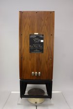
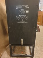
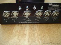
where I can order an angled xlr chassis connector as the last image show (also in use in Linn's S.A.R.A. from an early series) ?
Thanks for some advices.
The version without integrated crossover network boards (active version) works mostly with Naim Audio's NAXOS3/NAP250 at those days (check out the images in post #2).
http://mybriks.com/assets/pdf/HiFiNews_nov2011.pdf
Was in einem Paar Linn Isobarik drinn ist
Matthias (Linn Isobarik) - aktives-hoeren.de
Linn Isobarik - Lautsprecherabdeckungen / Loudspeaker Grilles
Linn Isobarik DMS Schaum Gitter Abdeckungen | eBay
A Linn Isobarik PMS clone for the 21st century?
Modified Linn Isobarik
And an other question:
where I can order an angled xlr chassis connector as the last image show (also in use in Linn's S.A.R.A. from an early series) ?
Thanks for some advices.
Attachments
-
 Linn Isobarik DMS first series front-IV.jpg94.7 KB · Views: 143
 -
 Linn Isobarik DMS first series 3x angle XLR terminal.jpg264.9 KB · Views: 652
 -
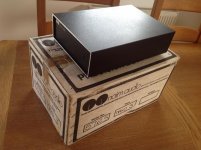
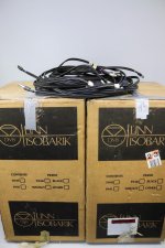 Linn Isobarik DMS first series package.jpg407.8 KB · Views: 219
 -
 Linn Isobarik DMS first series single angle XLR terminal.jpg236.8 KB · Views: 118
 -
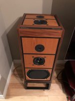
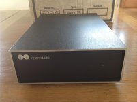
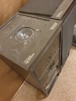 Linn Isobarik DMS first series top view.jpg272.9 KB · Views: 134
 -
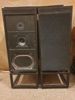 Linn Isobarik DMS first series front-II.jpg299 KB · Views: 439
 -
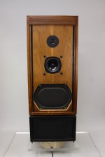 Linn Isobarik DMS first series front.jpg264.1 KB · Views: 124
 -
 Linn Isobarik DMS first series front-III.jpg76.6 KB · Views: 354
 -
Linn Isobarik History.pdf5.1 MB · Views: 118
Last edited:
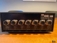
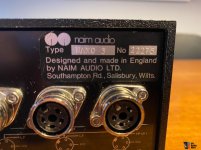
Images Naim Audio's NAXO3 - different chassis connectors on back panel.
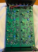
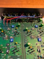
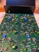
Are anywhere schematics available ?
Are anywhere schematics available ?
Attachments
-
 2izZARv.jpg117.1 KB · Views: 46
 -
 Naim Naxo 3-7.jpg107.9 KB · Views: 41
 -
 6rmtAoJ.jpg67.2 KB · Views: 79
 -
 2978452-f04f0eca-naim-naxo-3-6.jpg108.4 KB · Views: 87
 -
 2978453-dc9f864b-naim-naxo-3-6.jpg103.2 KB · Views: 88
 -
 2978454-0151bf83-naim-naxo-3-6.jpg88.3 KB · Views: 51
 -
 2978455-8d4b2fa2-naim-naxo-3-6.jpg79.1 KB · Views: 53
 -
 2978456-f58ed7d9-naim-naxo-3-6.jpg75.3 KB · Views: 42
 -
 2978451-67efc8f1-naim-naxo-3-6.jpg39.4 KB · Views: 63
 -
 Naim Audio NAXO3 Package.jpg129.2 KB · Views: 43
Don't know of any sites that describe this, but I have done it in the distant past. IIRC, the only access into the enclosure is through the bass drivers. All the drivers are not only bolted with T-nuts but also have liberal application of silicone sealer to ensure a complete air seal. That sealer is hard to break & means the drivers have to be pried off very carefully.I am looking for an URL, where are to find images concerning the disassembly procedure (how I open a not screwed version of this loudspeaker for repair/upgrade resp. remove the integrated crossover network boards and replace the internal KEF B139).
The method shown to Linn service dealers in the day was... to remove the Allen head bolts from the bass driver, take an appropriately sized sharp-threaded (wood??) screw with a large head, insert it carefully into one of the mounting holes of the bass driver, and engage the thread of the wood screw into the metal of the chassis in that hole. IIRC, the frame is cast aluminum. Once the screw is secure enough, a claw-hammer or similar tool is used to pry the driver slowly out from that corner by pulling on the protruding screw/bolt. A fair amount of leverage needed to be applied. Naturally, protective boards etc. need to be placed strategically over the driver and enclosure surfaces. Naturally, slipups were known to happen.
Last edited: