Jeah, one would need to test this to determine if there is meaningful difference and what is preferred. "The c-c rule" makes sense but since the listening environment is part of the equation one should consider/test what setup works better. Also as commented already, the spacing looks a bit weird and the looks is very important in home hifi.
Here is one of the Kimmosto posts, maybe the first, I don't have a log.
VituixCAD
There are many more, also in other forums. Google finds some with "kimmosto c-c". Basically it is just an observation made simulating with full 360 data so don't shoot the messenger")
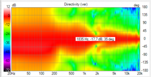
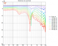
Some math for the standing up position:
3m listening distance and 90cm on axis height means that standing up (+1m) is about 18 degrees off-axis. I've got one version of xo sim where the nulls are at about 18 degrees (~1.4wl c-c) so it should be possible to point the null to standing height and test the audibitility pretty easily, need to check it out some day if there is difference.
More calculation to connect the issue with reality:
20cm above or below on-axis at 3 meters is about ~4 degrees off-axis so reaching for a coffee mug while seated shouldn't get you on the null. Reasoning from the example data the 1-1.4wl c-c seems to be mainly a stand-up position problem if any. Take one step closer or further and you have ~-10db instead of ~-20db. In reality it is rare to stand in the listening area (at least for me). Standing up happens while walking and doing chores, otherwise I'm in resting position Also, Hi Q dips are about the least audible EQ tricks, compared to any peak or wide Q.
Anyway, will definitely try test this, at least with sine wave it should be audible?
edit. added 90 deg limited linechart for another view on it.
Here is one of the Kimmosto posts, maybe the first, I don't have a log.
VituixCAD
There are many more, also in other forums. Google finds some with "kimmosto c-c". Basically it is just an observation made simulating with full 360 data so don't shoot the messenger
Some math for the standing up position:
3m listening distance and 90cm on axis height means that standing up (+1m) is about 18 degrees off-axis. I've got one version of xo sim where the nulls are at about 18 degrees (~1.4wl c-c) so it should be possible to point the null to standing height and test the audibitility pretty easily, need to check it out some day if there is difference.
More calculation to connect the issue with reality:
20cm above or below on-axis at 3 meters is about ~4 degrees off-axis so reaching for a coffee mug while seated shouldn't get you on the null. Reasoning from the example data the 1-1.4wl c-c seems to be mainly a stand-up position problem if any. Take one step closer or further and you have ~-10db instead of ~-20db. In reality it is rare to stand in the listening area (at least for me). Standing up happens while walking and doing chores, otherwise I'm in resting position
Also, Hi Q dips are about the least audible EQ tricks, compared to any peak or wide Q. Anyway, will definitely try test this, at least with sine wave it should be audible?
edit. added 90 deg limited linechart for another view on it.
Attachments
Last edited:
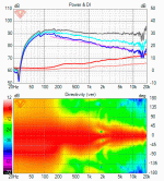
Forgot to mention both graphs are normalized.
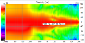
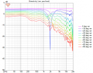
Here is for comparison as close as possible c-c, about 0.9wl. and gif showing the difference between the two, as close as possible situation at 0.9wl c-c and deliberate ~1.4wl c-c.
This is 8" mid and freestanding STH100 on top so I can actually change the c-c in reality and should be able to test if there is meaning full difference. But, it won't be blind test so
At least in this case and setup the graphs look nicer with the spacing on previous post. Main lobe is narrow there, but should be big enough for various body positions on a couch 3 meters away.
On the GIF, light red line is ERDI and red is DI, dark blue being the power response. Black is reference angle (0) and light blue is ER total.
Attachments are:
1. 0.9wl c-c polar plot normalized
2. 0.9wl c-c line chart 0-90 deg normalized
3. GIF showing the difference between 0.9 and 1.4wl c-c in previous post.
Attachments
Last edited:
Thanks a lot everyone for this really interesting discussion.
I am learning a lot.
But now I am also really confused about what is the better placement for mid.. Really close c2c or 1.2x kind of spacing as I did currently.
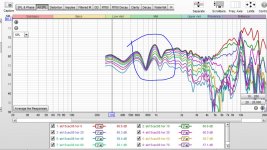
I am also confused about what is going on in the circled part for the mid measurement in the attached pic
I am learning a lot.
But now I am also really confused about what is the better placement for mid.. Really close c2c or 1.2x kind of spacing as I did currently.
I am also confused about what is going on in the circled part for the mid measurement in the attached pic
Attachments
Last edited:
My own limited experiments have shown me that a tweeter+mid sound best when they are placed as close together as possible. This may not be the most optimum arrangement for sound power considerations, or DI considerations, but in my room it has sounded best.
So I am in agreement with Pida and Augerpro
In my room, with my active DSP 3-way, a DSP filter which provides the flattest sound power response and smoothest DI response turns out NOT to be the best sounding filter. I have been pondering this fact for several weeks. Based on a careful reading of F. Toole, I believe that gross errors in DI / sound power are audible and damaging. Minor "errors" are not significant. My best-sounding DSP filter is not optimized for DI, but the errors are of the minor kind.
j.
Thank you.
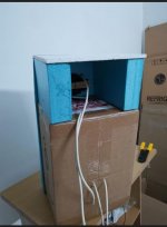
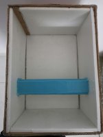
It is very embarrassing to show to due to the shoddy construction.. 😃 So I am hesitant.. But I will still post here.. the 10L cabinet for the mid is made of 10mm thick 5 ply cardboard +8mm thick foamcore sheet inside. I have used hot glue to seal every single gap. The front of the baffle is inserted into the box with an inner baffle made of same 8mm thick foam core. The 'cabinet ' is filled heavily with teased out polyfill.
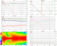
I did a ground plane measurement or whatever I have understood about ground plane measurement so far. This was just to focus on the probably 300-1.3kHz part. For now I measured with the mic only one meter away from the tilted down speaker. I could only make sure that a 2.5 square meter area around the measurement was clear of other things.
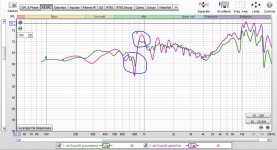
For comparison I lowered the ground plane measurement SPL by about 20 dB and plotted both the gated response with 7ms gate and the ground plane measurement gated around 12ms. Attached is a plot in which I have overlaied ground plane data I got with gated measurement data. It looks like there are high Q notches around the 800Hz frequency.
Now thinking about this I have a theory.. 😃 This cabinet could be very very resonant and leaking in the midrange frequencies. Maybe these are what are causing these high Q notches. However, since my DIY impedance measurement jig is damaged, I am not able to test this theory with it (I am in the waitlist for a dayton dats V3). Maybe I should pay much attention to these low freq responses with this cabinet due to above details, once a properly braced, well-damped cabinet is made, these will disappear..?
At the risk of sever embarassment, attached are pics of inside part and back of cabinet.
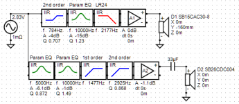
Also, to conclude this part of the experiments and focus on building the actual cabinets, I have tried to design a prototype crossover and resulting responses and attached them along with this post. I have only focused on the above 1kHz part of the spectrum as probably the measurements below it are unreliable.
Thanks
Vineeth
It is very embarrassing to show to due to the shoddy construction.. 😃 So I am hesitant.. But I will still post here.. the 10L cabinet for the mid is made of 10mm thick 5 ply cardboard +8mm thick foamcore sheet inside. I have used hot glue to seal every single gap. The front of the baffle is inserted into the box with an inner baffle made of same 8mm thick foam core. The 'cabinet ' is filled heavily with teased out polyfill.
I did a ground plane measurement or whatever I have understood about ground plane measurement so far. This was just to focus on the probably 300-1.3kHz part. For now I measured with the mic only one meter away from the tilted down speaker. I could only make sure that a 2.5 square meter area around the measurement was clear of other things.
For comparison I lowered the ground plane measurement SPL by about 20 dB and plotted both the gated response with 7ms gate and the ground plane measurement gated around 12ms. Attached is a plot in which I have overlaied ground plane data I got with gated measurement data. It looks like there are high Q notches around the 800Hz frequency.
Now thinking about this I have a theory.. 😃 This cabinet could be very very resonant and leaking in the midrange frequencies. Maybe these are what are causing these high Q notches. However, since my DIY impedance measurement jig is damaged, I am not able to test this theory with it (I am in the waitlist for a dayton dats V3). Maybe I should pay much attention to these low freq responses with this cabinet due to above details, once a properly braced, well-damped cabinet is made, these will disappear..?
At the risk of sever embarassment, attached are pics of inside part and back of cabinet.
Also, to conclude this part of the experiments and focus on building the actual cabinets, I have tried to design a prototype crossover and resulting responses and attached them along with this post. I have only focused on the above 1kHz part of the spectrum as probably the measurements below it are unreliable.
Thanks
Vineeth
Attachments


My own limited experiments have shown me that a tweeter+mid sound best when they are placed as close together as possible. This may not be the most optimum arrangement for sound power considerations, or DI considerations, but in my room it has sounded best.
So I am in agreement with Pida and Augerpro
In my room, with my active DSP 3-way, a DSP filter which provides the flattest sound power response and smoothest DI response turns out NOT to be the best sounding filter. I have been pondering this fact for several weeks. Based on a careful reading of F. Toole, I believe that gross errors in DI / sound power are audible and damaging. Minor "errors" are not significant. My best-sounding DSP filter is not optimized for DI, but the errors are of the minor kind.
j.
Thanks a lot.
Based on your's and all others opinions above I too am now thinking of making the mid as close as possible to tweeter in final cabinet.
Pic in post #53
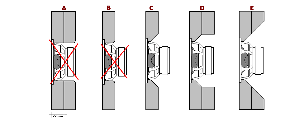
Thre is still 5cm extra distance between mid and tweeter. It is always best to place them as close as possible, specifically when listening distance is short(ish). The cutouts for driver bodies will leave enough material in-between, despite flanges touch each other.
Visual aspect is another question, but you have a good match in that respect IMO!
And I would like to tilt tweeter's response a bit higher from 8kHz up. Perhaps just WG-effect compensation might have higher dB setting in dsp?
Thank you.
I am now gravitating more towards making the mid closer to tweeter in final cabinet.
I have attached a prototype crossover with this focus only on 1kHz and above due to construction related issues with my cabinet which therefore might have caused unreliable measurements of the mid.
Please let me know if tweeter response tilting up is similar to what I have done with the prototype crossover in attached pic.
Attachments
Now thinking about this I have a theory.. 😃 This cabinet could be very very resonant and leaking in the midrange frequencies. Maybe these are what are causing these high Q notches. However, since my DIY impedance measurement jig is damaged, I am not able to test this theory with it (I am in the waitlist for a dayton dats V3). Maybe I should pay much attention to these low freq responses with this cabinet due to above details, once a properly braced, well-damped cabinet is made, these will disappear..?
Yes this is very plausible. If there is no cabinet stuffing (fiber or foam), there will be strong acoustical resonances, and these can transmit through the driver cone. There can also be structural resonances which cause these high Q notches. Either way,
... probably true.once a properly braced, well-damped cabinet is made, these will disappear.
Thank you..
Next thing I am going to do is do some basic research on good cabinet building techniques.. for midrange and the woofer.
I have read about some techniques it hereHAUPT)
I have also read through some of augerpro's studies on enclosure construction.
I am planning to have a single cabinet with separate sections for woofer and mid+tweeter.
For woofer, I am planning to have a 35L sealed cabinet. As per enclosure tool, it will give a Qtc = 0.707 for the woofer. Would a 1 inch thick well braced box of birch ply with above volume be good for this?
For midrange, I am planning to have a 10-12L box. This gives a close to Qtc=0.6 tuning. Could anyone advice me on the best technique for a box here? I have read that properly filling the box with damping material is more important than having non parallel walls etc.
For the baffle itself, I am planning to have two 25mm birch ply sandwiched together to form a 50mm thick sheet from which I can cut out the 30+ degree chamfers as seen in my foam model on top and bottom. Please advice on any good techniques. Again I only know that since the baffle is the launch platform for the drivers, it needs to be very stiff.
Thanks
Vineeth
Next thing I am going to do is do some basic research on good cabinet building techniques.. for midrange and the woofer.
I have read about some techniques it here
HAUPT) I have also read through some of augerpro's studies on enclosure construction.
I am planning to have a single cabinet with separate sections for woofer and mid+tweeter.
For woofer, I am planning to have a 35L sealed cabinet. As per enclosure tool, it will give a Qtc = 0.707 for the woofer. Would a 1 inch thick well braced box of birch ply with above volume be good for this?
For midrange, I am planning to have a 10-12L box. This gives a close to Qtc=0.6 tuning. Could anyone advice me on the best technique for a box here? I have read that properly filling the box with damping material is more important than having non parallel walls etc.
For the baffle itself, I am planning to have two 25mm birch ply sandwiched together to form a 50mm thick sheet from which I can cut out the 30+ degree chamfers as seen in my foam model on top and bottom. Please advice on any good techniques. Again I only know that since the baffle is the launch platform for the drivers, it needs to be very stiff.
Thanks
Vineeth
tmuuikku> I would be interested in your results of the sine wave test to determine audibility. I'm not against this concept, possibly it would be preferred under some circumstance. I just doubt it should be generally followed in all cases. I'll have to look into Kimmosto's work more, that linked post is really just making claims, I need to understand the conditions that underpin those claims.
HifiJim> your comment reminded me of another thing I haven't liked about tweeters too far from the mid and that was for voices and some instruments to "wander" back adn forth between drivers instead of sounding like they come from one point in space.
Vineeth> here's my quick and dirty recommendation on the box: at least do a simple CLD construction where you use two panels glued together with Weicon Flex 310M Classic (or SikaFlex 291 if you can't source the Weicon). This single factor made more difference in my testing than what wood you used or even the thickness.
CLD braces are also easy to do, so do that (see my website for examples, I'm testing some more today). I would apply Resonix tiles, but I'm not sure you can get that. Someone here can probably link a generic version for home construction. Beware they don't all perform the same though. Then I would line the walls with 100% wool batting for quilts at @ 1.5" thickness. You can find this online easily enough. I have a link to a Euro source at my website.
EDIT: just noticed you are doing sealed boxes. I still like the wool as fill for this. Or the type of dacron batting that Meniscus Audio sells.
^ Yes your doubt is right, the wl spacing trick depends on the listening environment. Point is to have same spectra on the early reflections as the direct sound.
I spent time for you and found few links that have free discussion about it. If you have time to read the few pages linked you'll get the rationale behind "the c-c rule", when it should be applied and where Kimmosto got the numbers.
Here the whole page kind of relates:
Some help with lobing | Page 2 | Audio Science Review (ASR) Forum
Here scroll down some to get to the relevant discussion
VituixCAD v2 - Page 6
I'm not very good explaining in english, hopefully these help
Last edited:
Thanks everyone for the tips so far.
@Augerpro: Thanks a lot. I will try to source the Weicon Flex or Sikaflex adhesives, but I fear it would very expensive here in India. The last time I checked, buying 1.5 litre volume of the adhesive will cost me more than both the tweeters combined. And the above volume of adhesive itself may not be enough to build two close to 60 -70L volume floor standing speaker boxes.
So I wanted to know if any general category of adhesives are preferred for this CLD application. If there is such a thing, maybe I can look at a brand which is more locally available.
Another question that I have is, on your website you had remarked that CLD box + CLD brace didn't complement each other as you had hoped. Does it mean that both need not/should not be used in a box construction application?
Or should the midrange box be made as a CLD box and the woofer box as a regular box with CLD bracing
Or can I make a full CLD box with separate partition for mid and CLD bracing applied more in the woofer compartment
I dont see the CLD tiles you mentioned available here yet. Maybe I can apply some sound dampening alubutyl sheets and hope for the best. Regarding wool/dacron for cabinet fill, I will definitely source this.
@Juhazi: Thanks for the chamfering tip. I will definitely do this. since the intended front baffle itself is about 50mm thick, chamfering will make a lot of sense with the mid driver and probably the woofer.
@tmuikku: Thanks again for providing all these posts showing Kimmosto's reasoning behind the 1.2x spacing rule. I am definitely learning more but also I just get confused more
At my home, I may probably never have a chance to listen to these speakers more than 2.5m away, since rooms are relatively small and walls are relatively close.Kimmosto himslef says close c-c/coaxial is better for nearfield listening. Is there any rule which specifies what is nearfield/farfield with respect to a home listening environment like mine..
I think the definition for nearfield listening is that the direct sound is louder than the reverberant sound from the room, but you would have to check the true meaning. This is relevant enough definition in this context I think.
The kimmosto c-c rule is basically related to the quality of the reflected sound. Reflected sound is not too important if you are nearfield or have acoustic treatment in your room, in other words reflected sound is minimized to the listening position.
The louder the first reflection (ceiling/floor) is the more relevant it is to mind about their sound signature. Here the c-c could matter, you could arrange the lobing so that the reflected sound (from ceiling and floor) has similar sound signature as the direct sound.
When there is big main lobe, drivers as close as possible c-c, the first reflections from ceiling/floor might happen through the off-axis null and will sound different than the direct sound. You can use the c-c distance adjustment as advantage in this situation by steering the off-axis null so that it is not on the way of first reflections. Now the first reflection from the ceiling/floor has similar sound as the on-axis. The CTA-2034 standard rates the off-axis, first reflection, sound very important in situation where it is prominent, explained in the quote few pages back.
I'd say you just have to build something and if it doesn't sound good enough you have a possibility to explore here.
Hope this clarifies it After all, it is just common sense thinking whether to use it or not. Reflected sound is very loud if there is no absorption on the surface. Turn your speaker around to point to a wall or ceiling, and the sound doesn't change much.
The kimmosto c-c rule is basically related to the quality of the reflected sound. Reflected sound is not too important if you are nearfield or have acoustic treatment in your room, in other words reflected sound is minimized to the listening position.
The louder the first reflection (ceiling/floor) is the more relevant it is to mind about their sound signature. Here the c-c could matter, you could arrange the lobing so that the reflected sound (from ceiling and floor) has similar sound signature as the direct sound.
When there is big main lobe, drivers as close as possible c-c, the first reflections from ceiling/floor might happen through the off-axis null and will sound different than the direct sound. You can use the c-c distance adjustment as advantage in this situation by steering the off-axis null so that it is not on the way of first reflections. Now the first reflection from the ceiling/floor has similar sound as the on-axis. The CTA-2034 standard rates the off-axis, first reflection, sound very important in situation where it is prominent, explained in the quote few pages back.
I'd say you just have to build something and if it doesn't sound good enough you have a possibility to explore here.
Hope this clarifies it
After all, it is just common sense thinking whether to use it or not. Reflected sound is very loud if there is no absorption on the surface. Turn your speaker around to point to a wall or ceiling, and the sound doesn't change much.
Last edited:
Thanks for the awesome explanation..
Your explanation makes a lot of intuitive sense to me..
In wireless communication, we do things like beam forming and beam steering with antenna arrays. Looks like here we are doing something similar to a simplified beam steering of the crossover band of frequencies using the mid and tweeter drivers. The beam steering here is done in such a way that the perceived sound balance across frequencies and especially in the crossover band at a listening position in the far-field of these radiators is similar to the on-axis sound beam of the crossover band.
Thanks.

vineeth> Look for MS Polymer based adhesives, or failing that, possibly simple latex. Find something with a Shore A Hardness in the low 40s. IF the datasheet doesn't list that, don't buy it. All of the silicone or polyurethane adhesives I've found cure too hard to damp vibration.
The hope is always that if CLD panels damp resonance X and CLD braces damp resonance Y, they will simply sum and you get the best of both worlds. But my concern early on was that this may not be the case, and was why I separated panel/enclosure tests from brace tests, to isolate those variables. In the end, I think the data show CLD panels plus CLD braces is the way to go on balance, but you can see that combining methods did not quite produce the results you might have predicted from the individual tests.
The hope is always that if CLD panels damp resonance X and CLD braces damp resonance Y, they will simply sum and you get the best of both worlds. But my concern early on was that this may not be the case, and was why I separated panel/enclosure tests from brace tests, to isolate those variables. In the end, I think the data show CLD panels plus CLD braces is the way to go on balance, but you can see that combining methods did not quite produce the results you might have predicted from the individual tests.
@Augerpro:
Thank you..
I found this adhesive locally with datasheet specifying shore A hardness = 35-45 (https://5.imimg.com/data5/UC/JN/MY-3773652/essr-bond-ms40.pdf). From the specs would this suffice?
This will cost me 5 times less than weicon flex 310M.
Thank you..
I found this adhesive locally with datasheet specifying shore A hardness = 35-45 (https://5.imimg.com/data5/UC/JN/MY-3773652/essr-bond-ms40.pdf). From the specs would this suffice?
This will cost me 5 times less than weicon flex 310M.
Yeah that looks perfect. I apply a uniform 1/32" thickness. To do this I use a fine square-tooth trowel that makes 1/16" square beads, then when I lay down a panel I push it "cross grain" to collapse those 1/16" beads into a 1/32" layer. Just like applying tile to a floor. However, I'm going to design a 3D printed trowel that will apply the 1/32" layer right from the start.
- Home
- Loudspeakers
- Multi-Way
- A 3 way design study