Actually I had only traced a single on-axes curve for each diver. All the off axis responses were generated using VituixCAD diffraction tool. As you rightly said even if I had taken all the off axis plots and do the sims using them, they will still differ based on my actual implementation of drivers in the cabinet. Hence I am stopping playing around with these plots and focus on more important things for now like taking steps to finalize the bass alignment, and building the speaker cabinet.
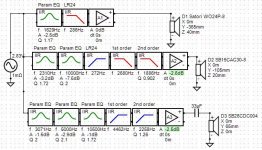
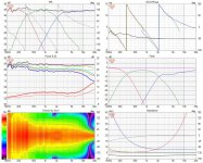
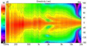
As a last attempt, I played with the crossover for a little more and the results are shown in attached plots. Whether it is of any use in actual practice is doubtful due to the probably unreliable nature of the data itself but this seems like the best results I could achieve so far.
Thanks
As a last attempt, I played with the crossover for a little more and the results are shown in attached plots. Whether it is of any use in actual practice is doubtful due to the probably unreliable nature of the data itself but this seems like the best results I could achieve so far.
Thanks
Attachments
I am trying to decide on a box volume for the Satori WO24P-8 woofer now.
I have been trying sealed alignments for this woofer. The maximum box volume that I can make is about 55L I think and a box of that size itself would occupy a significant space in my room which is about 3m wide by 3.5m in length with nearly 2.8m height. I can listen to speakers at about 2m away from them.
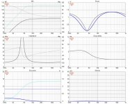
Please help me in finalizing on a good alignment for this woofer. For example I have used VituixCAD enclosure tool to generate specifications for two volumes given below
1) Box size such that its volume is 55L.
The vituixCAD six pack for this is attached as image-1
Here are other details:
STATISTICS
f3 48.3 Hz
f6 33.6 Hz
f10 24.5 Hz
Zmin 5.8 Ohm @ 329.4 Hz
Zmax 79.8 Ohm @ 39.4 Hz
GDmax 6.6 ms @ 17.1 Hz
XmaxC 2.5 mm @ 5 Hz
Pmax 1.4 VA @ 329.4 Hz
-------------------------------------------------------------
DRIVER: SB Acoustics SATORI WO24P-8, 1 pcs in series
n0 0.30 % Reference efficiency
SPL 87.0 dB/W Sensitivity
USPL 88.4 dB/2.83 Sensitivity
EBP 59.8 Efficiency bandwidth product
Dd 18.0 cm Effective diameter of driver
Vd 216.8 cm^3 Maximum linear volume of displacement
Cas 6.24E-7 m^5/N Acoustic equivalent of Cms
Mas 6.77E1 kg/m^4 Acoustic equivalent of Mms+Mme
Ras 1.83E3 Ns/m^5 Acoustic equivalent of Rms
Rae 2.6E4 Ns/m^5 Acoustic equivalent of Re+Rg
Lces 9.4E-2 H Electrical inductive equivalent of Cas
Cmes 4.49E-4 F Electrical capacitive equivalent of Mas
Res 8.25E1 Ohm Electrical resistive equivalent of Ras
-------------------------------------------------------------
BOX REAR 1: Vb=55.0 l, Ql=100.0
Fb 39.5 Hz System resonance frequency
Cab 3.89E-7 m^5/N Acoustic compliance of air in enclosure
Rab 1.03E2 Ns/m^5 Acoustic resistance due to absorption
Ral 1.03E6 Ns/m^5 Acoustic resistance due to leakage
Lceb 5.87E-2 H Electrical inductive equivalent of Cab
Reb 1.46E3 Ohm Electrical resistive equivalent of Rab
Rel 1.46E-1 Ohm Electrical resistive equivalent of Ral
Qtc 0.60 Total Q factor
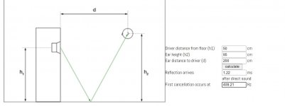
2) Box size such that volume = 45L
The vituixCAD six pack for this is attached as image-2
Other details:
STATISTICS
f3 47.6 Hz
f6 34.6 Hz
f10 25.6 Hz
Zmin 5.8 Ohm @ 329.4 Hz
Zmax 78.5 Ohm @ 42.4 Hz
GDmax 6.2 ms @ 22.4 Hz
XmaxC 2.2 mm @ 5 Hz
Pmax 1.4 VA @ 329.4 Hz
-------------------------------------------------------------
DRIVER: SB Acoustics SATORI WO24P-8, 1 pcs in series
n0 0.30 % Reference efficiency
SPL 87.0 dB/W Sensitivity
USPL 88.4 dB/2.83 Sensitivity
EBP 59.8 Efficiency bandwidth product
Dd 18.0 cm Effective diameter of driver
Vd 216.8 cm^3 Maximum linear volume of displacement
Cas 6.24E-7 m^5/N Acoustic equivalent of Cms
Mas 6.77E1 kg/m^4 Acoustic equivalent of Mms+Mme
Ras 1.83E3 Ns/m^5 Acoustic equivalent of Rms
Rae 2.6E4 Ns/m^5 Acoustic equivalent of Re+Rg
Lces 9.4E-2 H Electrical inductive equivalent of Cas
Cmes 4.49E-4 F Electrical capacitive equivalent of Mas
Res 8.25E1 Ohm Electrical resistive equivalent of Ras
-------------------------------------------------------------
BOX REAR 1: Vb=45.0 l, Ql=100.0
Fb 42.1 Hz System resonance frequency
Cab 3.18E-7 m^5/N Acoustic compliance of air in enclosure
Rab 1.19E2 Ns/m^5 Acoustic resistance due to absorption
Ral 1.19E6 Ns/m^5 Acoustic resistance due to leakage
Lceb 4.8E-2 H Electrical inductive equivalent of Cab
Reb 1.27E3 Ohm Electrical resistive equivalent of Rab
Rel 1.27E-1 Ohm Electrical resistive equivalent of Ral
Qtc 0.64 Total Q factor
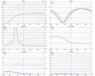
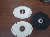
I would also like to know how much attention should I pay to thee position of the woofer on the baffle in regards to floor bounce related cancellations. For example, a quick calculation using this website: Floor/Ceiling Reflection Calculator gives me following details shown in attached image-3:
Thanks
I have been trying sealed alignments for this woofer. The maximum box volume that I can make is about 55L I think and a box of that size itself would occupy a significant space in my room which is about 3m wide by 3.5m in length with nearly 2.8m height. I can listen to speakers at about 2m away from them.
Please help me in finalizing on a good alignment for this woofer. For example I have used VituixCAD enclosure tool to generate specifications for two volumes given below
1) Box size such that its volume is 55L.
The vituixCAD six pack for this is attached as image-1
Here are other details:
STATISTICS
f3 48.3 Hz
f6 33.6 Hz
f10 24.5 Hz
Zmin 5.8 Ohm @ 329.4 Hz
Zmax 79.8 Ohm @ 39.4 Hz
GDmax 6.6 ms @ 17.1 Hz
XmaxC 2.5 mm @ 5 Hz
Pmax 1.4 VA @ 329.4 Hz
-------------------------------------------------------------
DRIVER: SB Acoustics SATORI WO24P-8, 1 pcs in series
n0 0.30 % Reference efficiency
SPL 87.0 dB/W Sensitivity
USPL 88.4 dB/2.83 Sensitivity
EBP 59.8 Efficiency bandwidth product
Dd 18.0 cm Effective diameter of driver
Vd 216.8 cm^3 Maximum linear volume of displacement
Cas 6.24E-7 m^5/N Acoustic equivalent of Cms
Mas 6.77E1 kg/m^4 Acoustic equivalent of Mms+Mme
Ras 1.83E3 Ns/m^5 Acoustic equivalent of Rms
Rae 2.6E4 Ns/m^5 Acoustic equivalent of Re+Rg
Lces 9.4E-2 H Electrical inductive equivalent of Cas
Cmes 4.49E-4 F Electrical capacitive equivalent of Mas
Res 8.25E1 Ohm Electrical resistive equivalent of Ras
-------------------------------------------------------------
BOX REAR 1: Vb=55.0 l, Ql=100.0
Fb 39.5 Hz System resonance frequency
Cab 3.89E-7 m^5/N Acoustic compliance of air in enclosure
Rab 1.03E2 Ns/m^5 Acoustic resistance due to absorption
Ral 1.03E6 Ns/m^5 Acoustic resistance due to leakage
Lceb 5.87E-2 H Electrical inductive equivalent of Cab
Reb 1.46E3 Ohm Electrical resistive equivalent of Rab
Rel 1.46E-1 Ohm Electrical resistive equivalent of Ral
Qtc 0.60 Total Q factor
2) Box size such that volume = 45L
The vituixCAD six pack for this is attached as image-2
Other details:
STATISTICS
f3 47.6 Hz
f6 34.6 Hz
f10 25.6 Hz
Zmin 5.8 Ohm @ 329.4 Hz
Zmax 78.5 Ohm @ 42.4 Hz
GDmax 6.2 ms @ 22.4 Hz
XmaxC 2.2 mm @ 5 Hz
Pmax 1.4 VA @ 329.4 Hz
-------------------------------------------------------------
DRIVER: SB Acoustics SATORI WO24P-8, 1 pcs in series
n0 0.30 % Reference efficiency
SPL 87.0 dB/W Sensitivity
USPL 88.4 dB/2.83 Sensitivity
EBP 59.8 Efficiency bandwidth product
Dd 18.0 cm Effective diameter of driver
Vd 216.8 cm^3 Maximum linear volume of displacement
Cas 6.24E-7 m^5/N Acoustic equivalent of Cms
Mas 6.77E1 kg/m^4 Acoustic equivalent of Mms+Mme
Ras 1.83E3 Ns/m^5 Acoustic equivalent of Rms
Rae 2.6E4 Ns/m^5 Acoustic equivalent of Re+Rg
Lces 9.4E-2 H Electrical inductive equivalent of Cas
Cmes 4.49E-4 F Electrical capacitive equivalent of Mas
Res 8.25E1 Ohm Electrical resistive equivalent of Ras
-------------------------------------------------------------
BOX REAR 1: Vb=45.0 l, Ql=100.0
Fb 42.1 Hz System resonance frequency
Cab 3.18E-7 m^5/N Acoustic compliance of air in enclosure
Rab 1.19E2 Ns/m^5 Acoustic resistance due to absorption
Ral 1.19E6 Ns/m^5 Acoustic resistance due to leakage
Lceb 4.8E-2 H Electrical inductive equivalent of Cab
Reb 1.27E3 Ohm Electrical resistive equivalent of Rab
Rel 1.27E-1 Ohm Electrical resistive equivalent of Ral
Qtc 0.64 Total Q factor
I would also like to know how much attention should I pay to thee position of the woofer on the baffle in regards to floor bounce related cancellations. For example, a quick calculation using this website: Floor/Ceiling Reflection Calculator gives me following details shown in attached image-3:
Thanks
Attachments
Last edited:
The only true small waveguide that I know of, is the same that I use - namely the Seas DXT:Thank you for the suggestions.
I am considering applying a waveguide on this tweeter. But I don't know which one to use in this scenario. I have only seen FM augerpro's elliptical-type waveguide for this tweeter, which looks a little big if I am going to use an avalon-type chamfered baffle.
H1499-06 27TBCD/GB-DXT
I found my inspiration for this tweeter among Heissmann's projects:
Heissmann Acoustics | Kits | Speaker developments
Thanks for pointing these resources.
I have gone through Heissman acoustics website in the past. I like his approach to speaker design mainly the diffraction control part using several methods and in particular using the combination of the waveguided DXT tweeter in combination with chamfered baffles. In fact, he site was my inspiration for trying to use chamfered baffle. I find that it also looks nice.
Unfortunately, the last piece of DXT tweeters available with the dealer in my country were sold out before I started this project and importing it will add a lot of cost. So I am unable to use it. Since I have the SB CDC tweeter in hand along with SB STAC tweeters, I thought I will use the CDC tweeter in a good implementation for now. I also find that the CDC tweeter along with its aluminum counterpart SB ADC have measurably low distortion performance, though I don't know subjectively how all of that will sound like. The only post that I have seen where the subjective opinions about this tweeter were written about is FM hifijim's posts on his speaker project.
You could do mockup of the box and test different edges. Use 2" foam panels for insulation on the sides for a cheap and easy way to compare. Try a big roundover vs chamfer.
I would add that the benefit you get from a waveguide is going to be greater than the difference between for example the 2" chamfer you might want, and the 1" chamfer you might have to use if you use a waveguide like mine. At least for sonic performance, aesthetics is a different matter.
I would add that the benefit you get from a waveguide is going to be greater than the difference between for example the 2" chamfer you might want, and the 1" chamfer you might have to use if you use a waveguide like mine. At least for sonic performance, aesthetics is a different matter.
Hi Sir!
Follow the L-R golden rule, have the same freq were bass meets mid etc. But I recommend 12db (24db usually sounds hard at tweeters). Also add a baffle step loss (a long slope on bass band to remove bulky sound).
If 12 db for all, be sure to invert the pole digitaly to midrange. You may also need to measure group delay for perfection with LR.
Last... make a cut in the low standing wave, if present in the room.
Last edited:
Hi,
Thank you for pointing out the LR crossover-related aspect. I have missed this. I just left the current frequencies on woofer and mid for LR just because I saw that the phases were tracking well. I will study more about this and will also consider it while I am designing the actual crossover.
These crossover design exercises above were to help myself gain some familiarity with VituixCAD to do a feasibility kind of study and to get valuable suggestions from forum members. I am very happy with how it has proceeded so far and I am definitely learning a lot.
Now I am bit more confident about this whole design process.
Thanks
Vineeth
Thank you for the suggestion.
I would definitely like to try this out.
Would you recommend the 5inch version of your waveguide for this setup where my mid is a 5inch driver?
Either the 4" or 5", depending on the crossover spec. Max width of the mounting flange is 4.8" for the 4" and 5.8" for the 5".
Thank you.
From the frequency response plots for the 4inch and 5 inch versions of the waveguide, I see that the 5inch is more suitable for a lower crossover point. The behavior above 2.5kHz looks the same for both waveguides. Since my intended use case is a 3 way application, I will try to get a 4inch version.
From the frequency response plots for the 4inch and 5 inch versions of the waveguide, I see that the 5inch is more suitable for a lower crossover point. The behavior above 2.5kHz looks the same for both waveguides. Since my intended use case is a 3 way application, I will try to get a 4inch version.
The only true small waveguide that I know of, is the same that I use - namely the Seas DXT:
H1499-06 27TBCD/GB-DXT
I found my inspiration for this tweeter among Heissmann's projects:
Heissmann Acoustics | Kits | Speaker developments
Thanks a lot for checking.
For now, I am planning to get a 4inch version of FM augerpro's waveguide design for this tweeter and try to study it for this application.
Here are the updates on this project. I have got the 4 inch elliptical waveguides for SB26CDC with phase shield. Now, I am trying to create a baffle for the tweeter and mid with similar width as the intended final width of the final cabinet with features like chamfers that i want to have in thd final baffle. I am trying to create this using insulation foam boards.
Before that i want to attach the tweeter to waveguide and i am a little concerned about my skills in this process. Could anyone advise a safe way to remove the tweeter faceplate and any tips for attaching the waveguide to the tweeter. The screw holes in the waveguide which are supposed to help attach the tweeter to it are not threaded right now. How can i get it done safely?
In general, kindly advise me on this process of attaching the waveguide to the tweeter. Waveguide pics attached
Attachments
Fun fun!
Regarding the tweeter, first take the four screws out. Have a butter knife handy. Next gently pull the faceplate up enough that you can see whether the diaphragm plate came with it or stayed with the driver. If it stayed you are good to go. If it comes off with the faceplate use the butter knife to gently pry the edge at a couple places and it will pop off. It's all pretty straightforward, just don't put stress on the leads and you will be fine. The driver body has 3 pins like the waveguide so putting the diaphragm plate back in place is easy.
As for mounting the tweeter, you will need to print or cut from wood the bar that is screwed to those two holes. I like fine thread machine screws, just work them in the holes they will thread themselves. And the most important part: use a piece of foam between the tweeter and bar, and tighten the screws just enough that driver won't move or settle. It doesn't need to be cranked down hard.
Last edited:
I've only just looked at this, but it seems as though there are guide marks on the waveguide, otherwise the faceplate would make a template. I'd drill the through holes from the back and then counterbore them. You can then back fill.
Ah, don't do that!

")
- Home
- Loudspeakers
- Multi-Way
- A 3 way design study