I’m posting this in response to Allen’s referencing of the speakers I’m building in another thread as an example of what can be wrong with a mtm! 
I'm building a $4000 speaker kit ... Which one?
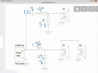
Allen I’ll link the crossover for the speaker in question and maybe you can help me understand how to improve on it? Drivers are…..
https://www.eminence.com/pdf/Delta_10B.pdf
https://www.bcspeakers.com/en/products/hf-driver/1-0/8/de250.pdf
http://gpoint-audio.com/wp-content/uploads/2013/03/seos10.jpg
I'm building a $4000 speaker kit ... Which one?
Allen I’ll link the crossover for the speaker in question and maybe you can help me understand how to improve on it? Drivers are…..
https://www.eminence.com/pdf/Delta_10B.pdf
https://www.bcspeakers.com/en/products/hf-driver/1-0/8/de250.pdf
http://gpoint-audio.com/wp-content/uploads/2013/03/seos10.jpg
Attachments
Last edited:
Good afternoon Bob, since you've chosen to pick that up I'll do what I can. It's necessary to know whether something can be done, or whether it should focus on smoothing what appears in the measurements. With what you've provided here I see some inconsistencies based on current information, and wonder how does the SEOS manage its vertical directivity (*). It's best that I keep this theoretical for the time being.
I know myself that it isn't obvious that there's a ceiling reflection until you learn to hear it.. so I hope saying that keeps this in perspective. The ceiling is undesirable as far as reflections go, when its response is lacking. While a cloud absorber can help there, the influence of vertical directivity can also make its way into the reverberant field.
The first part of crossing is acoustic. The two Ms are producing an asymmetric radiation pattern. The waveguide needs to match this and at the same time keep the crossover frequency the same for vertical and horizontal. Unless this happens then there may not be a proper electrical crossover available.. There may be wiggle room if you can determine a reasonable compromise.
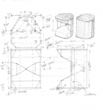
* Using conventional techniques virtually the entire waveguide design can be derived from these constraints. It won't be flat on the front. If you design a waveguide more narrow than another, but for working down to the same frequency, it will be taller and longer. Here is an example - Square Pegs
I know myself that it isn't obvious that there's a ceiling reflection until you learn to hear it.. so I hope saying that keeps this in perspective. The ceiling is undesirable as far as reflections go, when its response is lacking. While a cloud absorber can help there, the influence of vertical directivity can also make its way into the reverberant field.
The first part of crossing is acoustic. The two Ms are producing an asymmetric radiation pattern. The waveguide needs to match this and at the same time keep the crossover frequency the same for vertical and horizontal. Unless this happens then there may not be a proper electrical crossover available.. There may be wiggle room if you can determine a reasonable compromise.
* Using conventional techniques virtually the entire waveguide design can be derived from these constraints. It won't be flat on the front. If you design a waveguide more narrow than another, but for working down to the same frequency, it will be taller and longer. Here is an example - Square Pegs
Attachments
Thanks Allen,
Well here’s some things I do know for sure……the fr response measurements I’ve posted for these mtm were done outside on a 10 foot ladder so there is no influences in them.
Like you’ve said before there are height constraints for the horn/waveguide to keep the m’s ctc as close as possible. If that distance is already too much for a 1500 Hz crossover I may be able to make a new baffle that overlaps into waveguide like I’ve seen done……might be able to reduce ctc by a inch or so. Only problem is these waveguides are now unobtainable and I’d hate to screw them up! I’m not opposed to purchasing another set of horns to experiment with, but which one in the sea of choices!? This could be a choice that I could also cut reliefs into for the mids without despair. ME20 Horns - B&C Speakers
B&C ME20 is a 1" high frequency horn - B&C ME20 cast aluminum horn - B&C 1" high frequency bolt-on type horn. B&C ME20 high frequency horns available now.
My ceilings are tall and irregular, floor is hard tile and wife doesn’t want rugs. (two 100lb dogs that shed a poodle every two days!) mtm were an attempt to control the verticals is why I’m trying these in the first place.
Appreciate the help, of course I will be trying them in stock form to get a baseline…….probably looking at around end of august for that.
Also I will be taking not only the typical 1w 1m measurements but also at lp in order to fine tune things even better for my room/setup. I know some frown on that but it makes perfect sense to me and I had some excellent results building my last speakers crossover in that fashion.
And as far as the super tweeters should they be designed into the xo or just played with later as frosting on the cake? I was thinking maybe a small inductor parallel on the tweeter to knock down the top end to blend the amt easier. I know this would change the phase relationship but not sure if that would be detrimental? Would a super tweeter on top then make this a tmtm? I can’t find any references to a build as such so it’s probably not a good idea, but I have seen super tweeters used successfully on mtm.
I will roll whatever way you see fit with or without super tweeters in the redesign, although I will be adding them (they are already purchased) and will probably end up getting another couple styles to compare. Seems they are a rather subjective preference.
Edit; forgot to mention the lack of bottom end on these mtm are not an issue as they will be sitting atop a 15” bass module (eminence lab 15’s) ……I say bass module because they will not go as low as a typical subwoofer. This will be blended in dsp so not really part of the xo……Guess it’ll be a tmtmw !
Last edited:
I'm glad to hear that because it may take some iterations to find what you need. I'm surely talking at a different pace.Appreciate the help, of course I will be trying them in stock form to get a baseline……
It's counterintuitive, I mentioned all those things so the reader would see that there is no correct answer in this particular configuration, only optimal ones. If I were constrained to making an MTM, my preference would be to increase the spacing to give way to the waveguide if needed.Like you’ve said before there are height constraints for the horn/waveguide to keep the m’s ctc as close as possible
Where you are actually constrained, however, is in where your ceiling and speaker are. It would be interesting for you to know the angle of the ceiling reflection.
What a super tweeter does is to alter the directivity, that's what it boils down to. You can add it to widen this, or you can cross to it if your current directivity is wrong and you want to change it.And as far as the super tweeters should they be designed into the xo or just played with later as frosting on the cake?
Maybe it's a simple matter of finding the way to put phase back where it should be.I know this would change the phase relationship but not sure if that would be detrimental?
“I’m surely talking at a different pace”
Is that Australian for ….’you move too dang slow Bob’ ? I hear that from my wife all the time!
“It would be interesting to know the ceiling angle”
I forget the exact pitch of that roof but it’s roughly 22 deg.
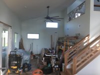
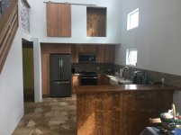
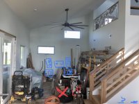
Just measured more exact…..Room is 13’6” across front wall x 30’ to rear wall, 9’6” tall left wall, 14’ tall right wall (open to loft at top) then open to kitchen around the stairs. (See pics) don’t mind the mess….still working!
LP will be centered roughly 9’ back…..that will place rear wall 21’ behind listener.
Deal I made with wife is that I can do whatever I want with that front wall and out 30” nothing out in the room (subs etc), no room treatments. (Although I am in negotiations over curtains on the left hand window and a tapestry on the right hand wall)
Is that Australian for ….’you move too dang slow Bob’ ? I hear that from my wife all the time!
“It would be interesting to know the ceiling angle”
I forget the exact pitch of that roof but it’s roughly 22 deg.
Just measured more exact…..Room is 13’6” across front wall x 30’ to rear wall, 9’6” tall left wall, 14’ tall right wall (open to loft at top) then open to kitchen around the stairs. (See pics) don’t mind the mess….still working!
LP will be centered roughly 9’ back…..that will place rear wall 21’ behind listener.
Deal I made with wife is that I can do whatever I want with that front wall and out 30” nothing out in the room (subs etc), no room treatments. (Although I am in negotiations over curtains on the left hand window and a tapestry on the right hand wall)
Attachments
LOL.“I’m surely talking at a different pace”
Is that Australian for ….’you move too dang slow Bob’ ? I hear that from my wife all the time!
In any case, I meant the angle off the speaker for the reflection. If you put a mirror on the ceiling, which way is it looking at you. (Granted each side will be different, you're after the smallest angle of the two.)
Attachments
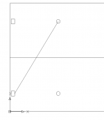
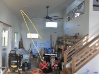
I think I’d only be able to ‘see’ the right speaker (if at all) in that scenario only if looking far fwd/left. Angle would be roughly 45 deg. Maybe less.
Edit….I know that looks more like 22 deg but it compressed by the viewpoint of pic
Edit….I know that looks more like 22 deg but it compressed by the viewpoint of pic
Attachments
Last edited:
Choice of speaker placement is non negotiable as per original WAF contract!
I have a foot or two side to sides and about a foot in/out from front wall, so basically what you see in the pic is what I got. She tells me I’m lucky to have that…..my response was considering I’m building you a house would make you (wife) the lucky one!
I have a foot or two side to sides and about a foot in/out from front wall, so basically what you see in the pic is what I got. She tells me I’m lucky to have that…..my response was considering I’m building you a house would make you (wife) the lucky one!
Thx vonAh, the speakers aren’t open baffle and the flexibility will be +/- a foot, actual distance from front wall will start @ 20” or so.
I have thought about putting the baffle together before box assembly and screw a stand on it just to see what open baffle might sound like (i know it wouldn’t be optimal, more of a ‘for giggles’ thing)
I have thought about putting the baffle together before box assembly and screw a stand on it just to see what open baffle might sound like (i know it wouldn’t be optimal, more of a ‘for giggles’ thing)
- Home
- Loudspeakers
- Multi-Way
- Crossover for 10” mtm